4245
On the Analysis of EPI Phase Correction with Small Tip Angle Excitation to reduce minimum required TE: Application to Whole-Brain Submillimetre-Resolution fMRI at 3T1Institute of Neuroscience and Medicine, Medical Imaging Physics (INM-4), Forschungszentrum Juelich, Juelich, Germany, 2Faculty of Medicine, Department of Neurology, JARA, RWTH Aachen University, Aachen, Germany
Synopsis
EPI has been widely used for fMRI due to its relatively fast imaging speed. However, as one of its drawbacks, ghost artefacts need to be corrected. In the community, an approach that utilises three non-phase encoded navigator echoes is commonly used for the correction. Although this scheme is quite effective, as the matrix size increases for high-resolution imaging the navigator echoes constitute a significant contribution in increasing the minimum required TE. To overcome this issue, this work employs an alternative navigator echo scheme. Here, its performance was analysed and whole-brain submillimetre-resolution fMRI (0.75 × 0.75 mm2) was demonstrated at 3T.
Purpose
EPI has been widely used for fMRI due to its relatively fast imaging speed. However, as one of its drawbacks, ghost artefacts need to be corrected. In the community, an approach that utilises three non-phase encoded navigator echoes is commonly used for the correction. This scheme has been shown to be robust and effective in removing the artefacts. However, as the matrix size increases for high-resolution imaging, the navigator echoes play a significant part in increasing the minimum required TE. To overcome this issue, this work proposes to employ an alternative scheme which allocates the navigator echoes in a preceding, separated TR loop.1 This scheme has not yet been analysed in terms of the steady-state and optimal flip-angle. The purpose of this study is to perform analysis for the aforementioned issues and demonstrate the method for submillimetre-resolution fMRI at 3T.Materials and methods
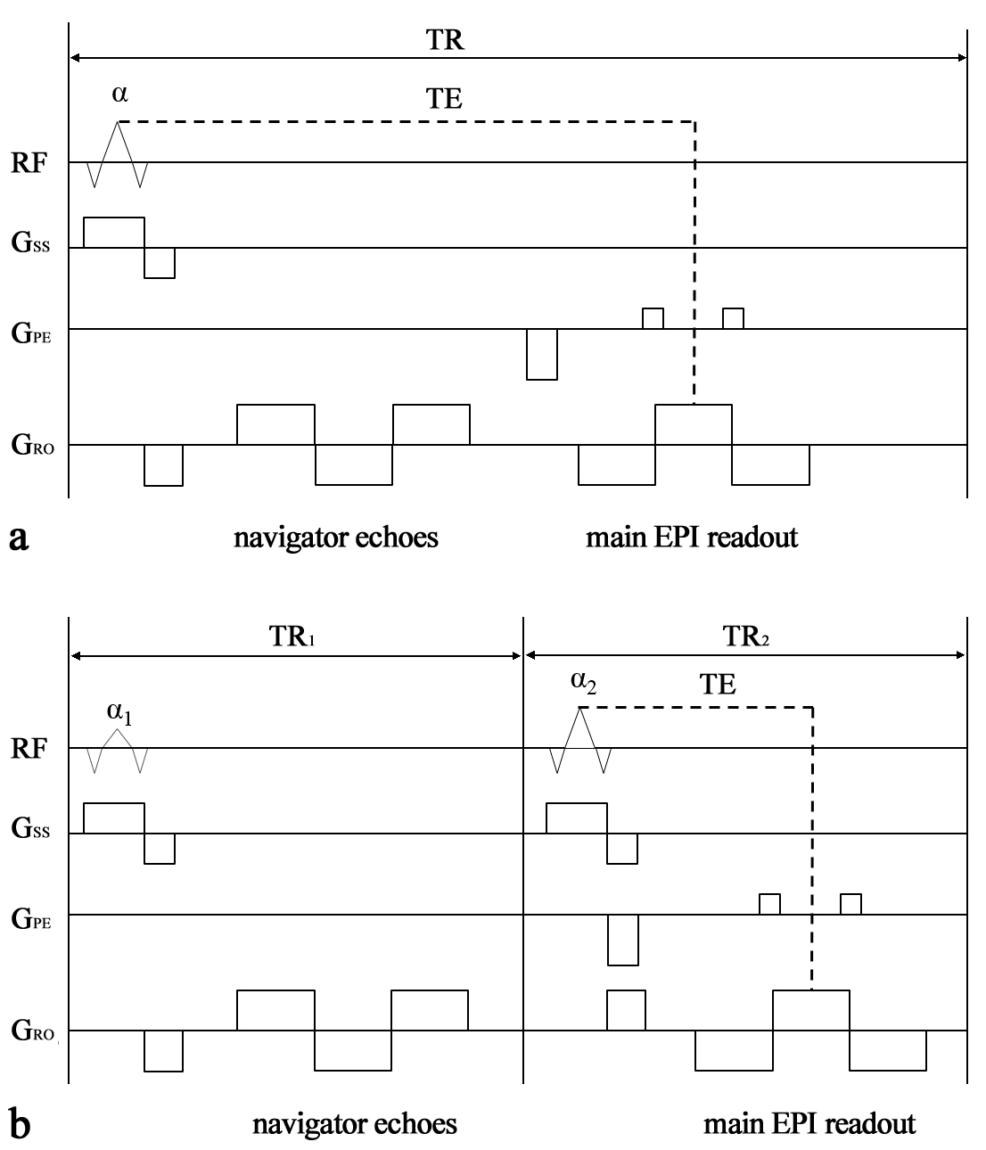
Figure 1 shows two different navigator echo schemes for EPI: one with the ‘navigator echoes’ in the same TR loop as the ‘main EPI readout’ (standard; see Fig. 1a) and the other with the ‘navigator echoes’ in a separated TR loop (alternative; see Fig. 1b). As shown here, the alternative scheme requires additional excitation (flip angle of α1) for the navigator echoes, which leads to a slight increase in scanning time. However, in contrast to the standard scheme, the navigator echoes do not have any impact on the increase of minimum required TE. This implies that a larger number of EPI echoes can be allocated until the given optimal TE for fMRI. Here, in order to check if the alternative scheme reaches a steady-state, the equation for the longitudinal magnetisation was derived under the ‘steady-state incoherent’ condition (i.e. elimination of remaining transverse magnetisation by spoiling).2 The derived equation is given as follows:
$$ M_{z(n)}^{alt}(0^{-})=M_{eq}\cdot\left[(E_{TR1}\cdot \cos \alpha_{1})^{n-1}\cdot(E_{TR2}\cdot \cos \alpha_{2})^{n-2}+(1-E_{TR1})\cdot\frac{1-(E_{TR1}\cdot \cos \alpha_{1}\cdot E_{TR2}\cdot \cos \alpha_{2})^{n-1}}{1-(E_{TR1}\cdot \cos \alpha_{1}\cdot E_{TR2}\cdot \cos \alpha_{2})}\\+(1-E_{TR2})\cdot(E_{TR1}\cdot \cos \alpha_{1})\cdot\frac{1-(E_{TR1}\cdot \cos \alpha_{1}\cdot E_{TR2}\cdot \cos \alpha_{2})^{n-2}}{1-(E_{TR1}\cdot \cos \alpha_{1}\cdot E_{TR2}\cdot \cos \alpha_{2})}\right] $$
where Mz(n)alt(0-) and Meq denote the longitudinal magnetisation just before the second TR loop excitation (α2) and the magnetisation at thermal equilibrium, respectively. Moreover, ETR1 and ETR2 indicate exp(-TR1/T1) and exp(-TR2/T1), respectively. For the standard scheme, as it is well-known from previous works,3 the equation is given as follows:
$$ M_{z(n)}^{std}(0^{-})=M_{eq}\cdot\left[(E_{TR}\cdot \cos \alpha)^{n-1}+(1-E_{TR})\cdot\frac{1-(E_{TR}\cdot \cos \alpha)^{n-1}}{1-(E_{TR}\cdot \cos \alpha)}\right] $$
where ETR denotes exp( -TR/T1).
Results
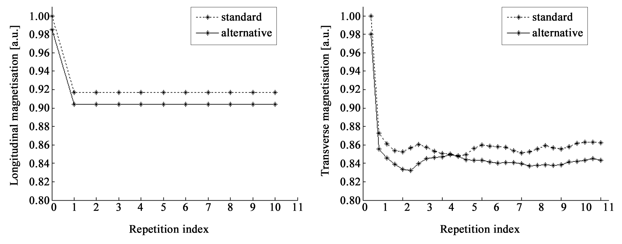
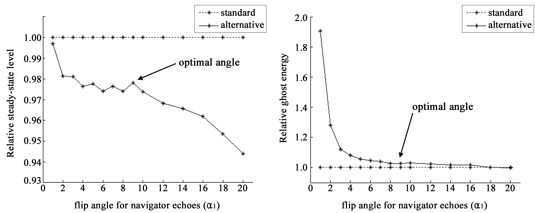
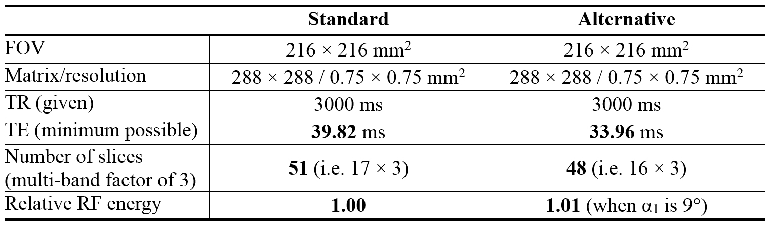
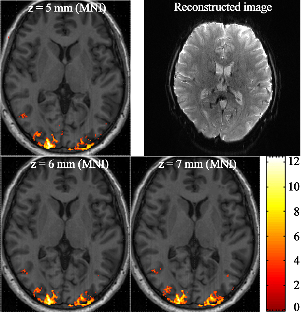
The two equations above were simulated under the following conditions: α/α1/α2 = 90/10/90°, TR/TR1/TR2 = 3000/10/2990 ms and T1 = 1.2 s. The results are plotted in Fig. 2a. It reveals that the signals are saturated to a certain level (i.e. steady-state) in both the standard and the alternative schemes. This was further verified with real in vivo data obtained with the same conditions. As shown in Fig. 2b, the signal behaviour is quite similar to the simulation data; although the real signals present transverse magnetisation in contrast to the above equations, the evolution of the transverse magnetisation is congruent with that of the longitudinal magnetisation. Here, in the alternative scheme, an optimal flip angle for navigator echoes (α1) was determined based on the steady-state level and the performance of ghost artefact removal. Figure 3 depicts in vivo data results where it is observed that as α1 increases, the stead-state level decreases, but the performance of ghost removal enhances (i.e. remaining ghost energy decreases). Nine degrees is a good compromised value for both issues. For this angle, the steady-state level of the alternative scheme is about 98% of that of the standard scheme and the performance of ghost removal is also quite similar each other. For the determined optimal angle, a high-resolution visual fMRI study was performed with the following settings: TR/TE = 3000/35 ms, FOV = 216 × 216 mm2, matrix = 288 × 288 (0.75 × 0.75 mm2), partial Fourier = 5/8, 2-fold in-plane/3-fold inter-plane (multi-band) acceleration and 48 slices with 2.3 mm thickness. Here, the minimum possible TE of the alternative scheme was 5.86 ms shorter than that of the standard scheme (see Fig. 4). Figure 5 shows a representative reconstructed image and three slices from a structural scan with activated regions superimposed on them. It is observed that the activated voxels are precisely localised along with the cortical regions, which successfully demonstrates high-resolution mapping.Conclusions
In this work, an alternative navigator echo scheme was analysed in terms of evolution of longitudinal magnetisation, steady-state level and the performance of ghost artefact removal. The method was shown to be effective in decreasing the minimum required TE and was demonstrated for whole-brain submillimetre-resolution fMRI.Acknowledgements
No acknowledgement found.References
- Wielopolski PA. Echo-planar imaging pulse sequences in Echo-planar imaging theory, technique and application, ed. Schmitt F, Stehling MK, Turner R. 1998. p. 96.
- Chen YN, Haacke EM. Current Protocols in Magnetic Resonance Imaging. John Wiley & Sons, Inc. 2001. B5.1.1-B5.1.16.
- Gescheidtova E, Bartusek K. Longitudinal Relaxation Time Measurement in MR with Transient-state Magnetization. 2008;4(1):61-64.
Figures