4241
Improving Image Quality of A Spiral T1 Spin-Echo Sequence1Barrow Neurological Institute, Phoenix, AZ, United States, 2Philips Healthcare, Cleveland, OH, United States
Synopsis
Cartesian SE is widely used for T1 imaging, but is slow and often susceptible to flow artifacts. A spiral T1SE technique has been proposed for rapid T1 imaging with minimal flow artifacts. However, inconsistent through-plane signal has been observed with certain protocols. In this work we investigate the root causes and propose a combined RF/gradient chopping scheme to minimize this inconsistency, and improve the T1 contrast. The improvement was demonstrated with phantom and volunteer data.
Introduction
T1 weighted spin-echo (T1SE) imaging is often used in the diagnosis of many neuro pathologies, especially when contrast agent is administrated. Recently a spiral T1SE technique has been proposed for rapid imaging with minimal flow artifacts (1). In T1SE, stimulated echo (STE) can arise from a group of three RF pulses, which may cause undesirable artifacts such as though-plane signal inconsistency. In this work, we investigate the root causes and propose a combined radio frequency (RF) pulse and gradient chopping scheme to minimize these artifacts in spiral T1SE. Meanwhile, this scheme is also designed to help improve the T1 contrast.Theory and Methods
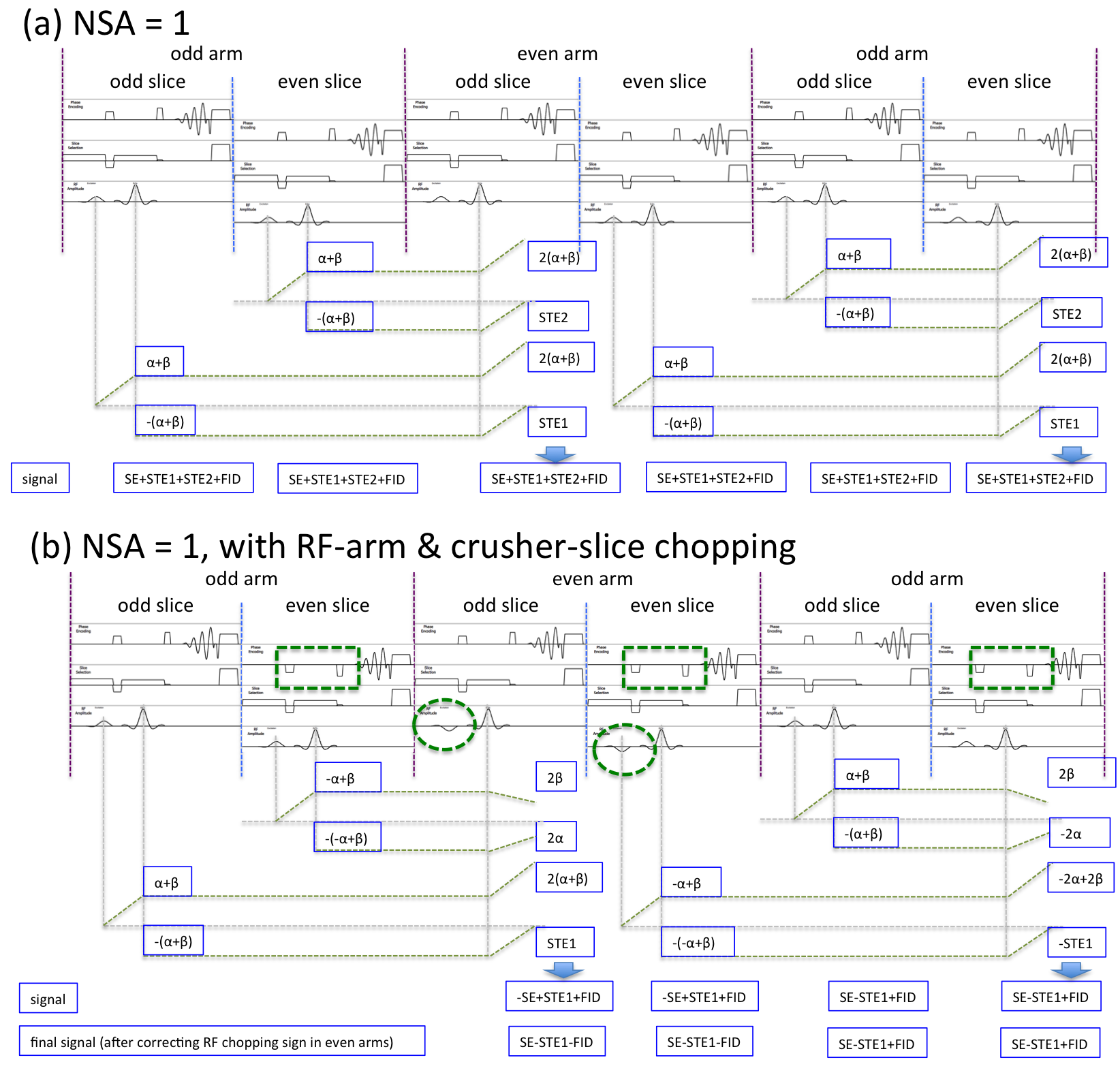
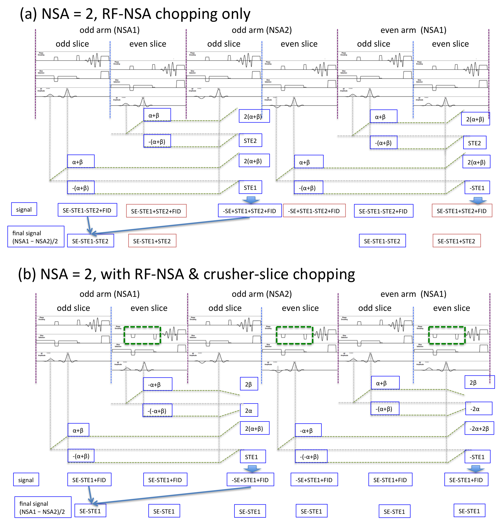
As shown with the extended phase graphs (2) in Figs. 1 and 2 (Fig. 1 for NSA (number of signal average) = 1, and Fig. 2 for NSA = 2), there are two major sources of STE in T1SE due to the imperfect slice profile. The first, STE1, is caused by the RF pulses exciting/refocusing (90°-180°) one slice and later refocusing (180°) the same slice in the next shot. To help visualize the phase evolution, 𝛼 is defined as the phase accumulated due to the in-plane crushers between excitation and refocusing, while 𝛽 due to the through plane crusher. The second, STE2, is produced following the RF pulses exciting/refocusing (90°-180°) a neighboring slice and subsequently refocusing (180°) the acquired slice. As a consequence, in the 1-NSA protocol (Fig. 1a), the signal for all spiral arms in all slices includes not only the desired SE, but also the undesired STE1, STE2, as well as any unsuppressed residual free induced decay (FID) signal. With a 2-NSA scan (Fig. 2a), however, odd and even slices have different signals, SE-STE1+STE2, and SE-STE1-STE2, respectively, due to the commonly used RF chopping with respect to NSA (RF-NSA). Note that the default RF-NSA chopping is used to cancel out the FID. This signal difference causes though-plane signal variation in 2-NSA scans. Furthermore, our investigation also reveals that subtracting STE from the signal help increase the T1 contrast.
To improve the image quality of spiral T1SE, we propose a combined RF/in-plane crusher gradient chopping scheme, as shown in Figs. 1b and 2b. Previous studies have been conducted on the interference of STE in Cartesian TSE and the the through-plane crusher gradient has been explored to mitigate the impact (3,4).
1-NSA scan
For a 1-NSA scan, the aim is to improve the contrast. RF chopping with respect to spiral arm (RF-arm) is used to subtract STE1 in the final signal (Fig. 1b). In addition, an in-plane crusher gradient chopping with respect to odd/even slice number (crusher-slice) is adopted (with a typical interleaved slice ordering) to minimize/eliminate STE2 (Fig. 1b), depending on the crusher gradient areas. The different contribution from residual FID (already reduced by the crushers) in odd and even arms will manifest as incoherent noise in both odd and even slices, and therefore will not cause through-plane signal inconsistency.
2-NSA scan
For a 2-NSA scan, the goal is to minimize the through-plane signal inconsistency. The crusher-slice chopping is added to the existing RF-NSA chopping (Fig. 2b). Similar to the 1-NSA case, the contribution from STE2 is minimized/removed. The FID is cancelled out by the default RF-NSA chopping. Consequently, consistent signal through all slices is achieved.
This new chopping scheme was implemented on a Philips 3T Ingenia scanner. Phantom and volunteer data were acquired to demonstrate its performance. The phantom consists of two bottles filled with gel, with T1 and T2 close to gray and white matters.
Results and Discussions
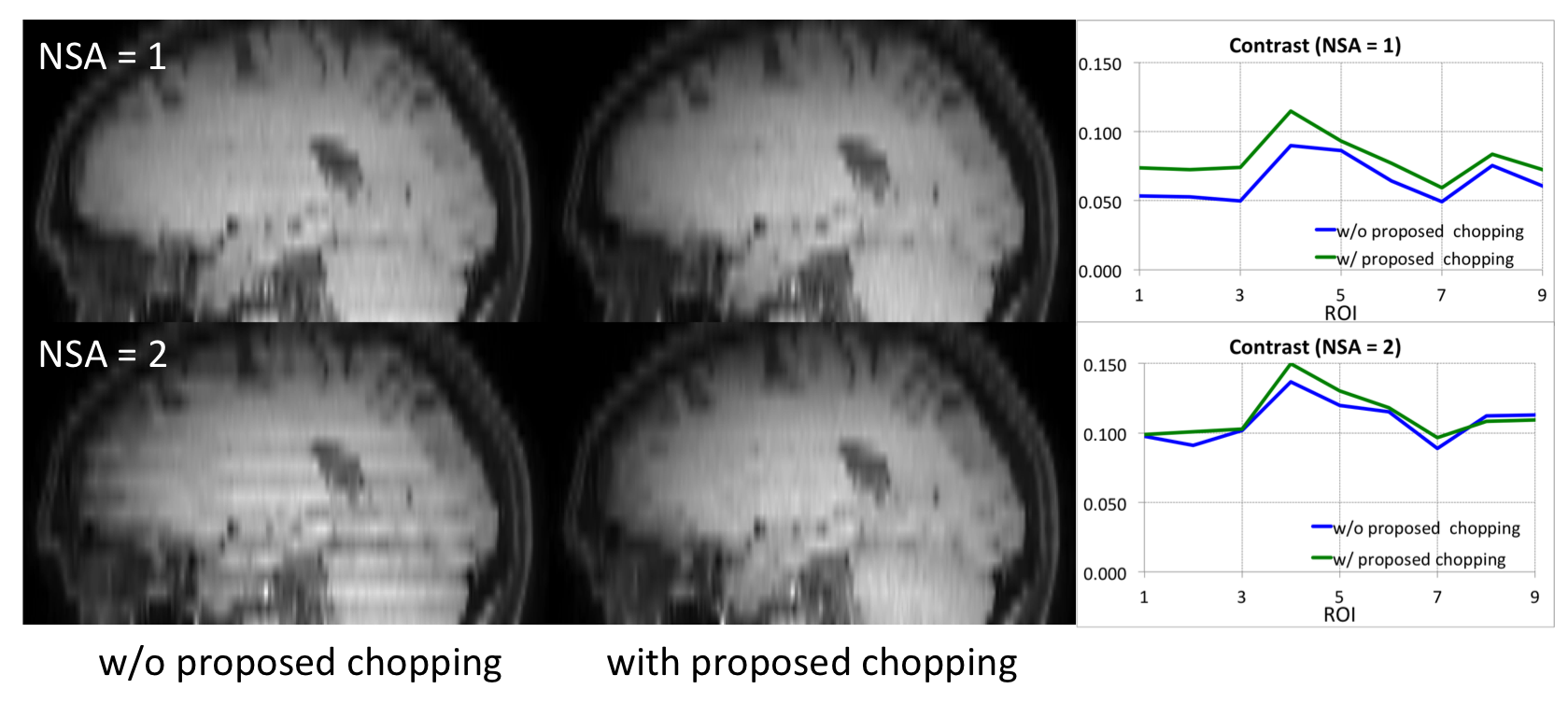
Phantom results without and with the proposed chopping scheme are shown in Fig. 3. With a 1-NSA protocol (top), the proposed RF-arm/crusher-slice chopping improves the contrast (Fig. 3b, measured as (signal 1 - signal 2)/(signal 1 + signal 2)). There is no noticeable negative impact on through-plane signal (Fig. 3a, reformatted sagittal image), except for the expected slight reduction in signal intensity due to the subtraction of STE1 and the reduction of STE2. For a 2-NSA scan (bottom), the through-plane signal inconsistency is minimized (Fig. 3c), without impacting the contrast (Fig. 3d).
Fig. 4 demonstrate the performance with in vivo data, which is consistent with the phantom experiment.
Conclusion
In this work, the proposed chopping scheme reduces the through-plane signal inconsistency in a 2-NSA spiral T1SE scan, and improves the contrast in a 1-NSA protocol.Acknowledgements
This work was funded by Philips Healthcare.References
(1) Li Z, Hu HH, Miller JH, et al. A Spiral Spin-Echo MR Imaging Technique for Improved Flow Artifact Suppression in T1-Weighted Postcontrast Brain Imaging: A Comparison with Cartesian Turbo Spin-Echo. Am J Neuroradiol. 2016; AJNR.A4600.
(2) Hennig Jürgen. Echoes - How to Generate, Recognize, Use or Avoid Them in MR-Imaging Sequences. Part I: Fundamental and Not So Fundamental Properties of Spin-Echoes. Concepts in Magn Reson. 1991;3:125-143.
(3) Crawley AP, Henkelman RM. Errors in T2 Estimation Using Multislice Multiple-Echo Imaging. Magn Reson Med. 1987;4:34-47.
(4) Feinberg D, Günther M. Method and Apparatus for Removing Specific Stimulated Echoes in Simultaneous Image Refocusing. US Patent: US006853188B2, 2005.
Figures