4239
Fast BLADE with variable flip angle1SIEMENS Healthineers, Shenzhen, China
Synopsis
An effective approach with variable flip angle to speed up BLADE acquisition is proposed for general MR imaging. It improved the efficiency of BLADE by enlarging the width of one blade. The image quality is comparable with that of conventional BLADE method.
Introduction
BLADE is an MR imaging method based on multi-shot turbo spin echo (TSE). It is less sensitive to bulk motion than conventional TSE [1]. But for uncooperative patients, some kinds of motion still can’t be corrected with BLADE method. These motion artifacts will obscure the pathology and cause incorrect diagnosis. Therefore it is necessary to speed up BLADE to alleviate motion artifacts. Although Turboprop was proposed [2], the imaging speed of BLADE is still limited by T2 decay in practical situations. Nevertheless, T2 decay can be overcome by employing variable flip angle (VFL) technique.Method
From the following equation adopted in BLADE
N*L=π*M/2 (1)
the scan time of one slice can be determined by
N*TR=π*M*TR/2 (2)
Where N is the number of strip (blade), L is the width of one strip, M is the effective matrix diameter and TR is the repetition time of one shot. From equation (2), the acquisition time of BLADE can be reduced by utilizing enlarged L, as proposed in Turboprop.
Obviously, T2 decay will become a real challenge when larger L is utilized. In order to mitigate T2 decay, one method was proposed to reduce the echo spacing of TSE by using shorter duration refocusing pulses. But this method has very little benefit to mitigate T2 decay due to the reduction of echo spacing not too much.
On the other hand, variable flip angle is one technique of reducing specific absorption rate (SAR) and render relatively steady signal evolution [3]. T2 decay can be healed by signal modulation. That is to say, the signal can be modulated to reduce T2 decay by variable flip angle in BLADE. Firstly, the array of flip angles is calculated via so-called extended phase graph algorithm [4]. And then the variable flip angle set is applied to BLADE to drive the signal to evolve smoothly. After abating T2 decay, the width of strip L can be increased and the acquisition time of BLADE will be reduced.
Results
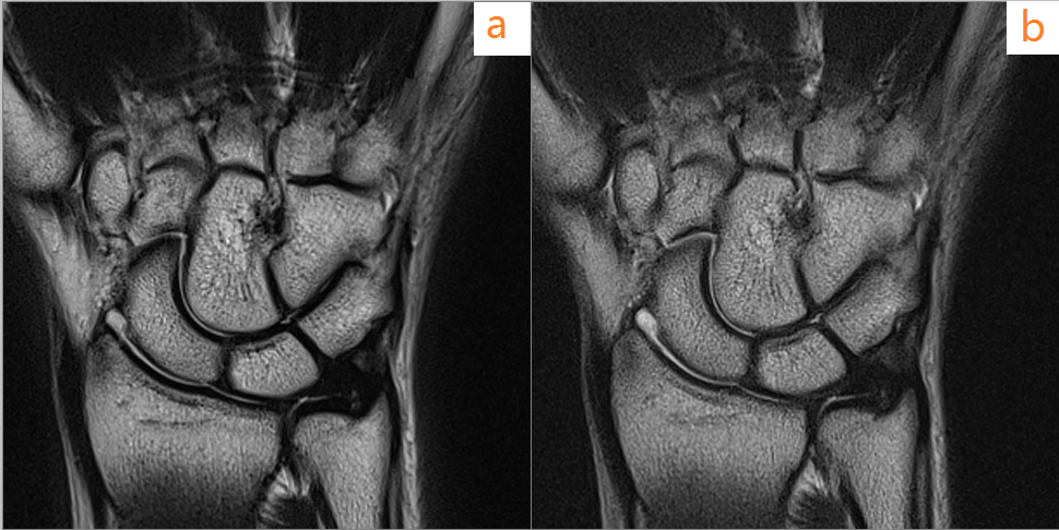
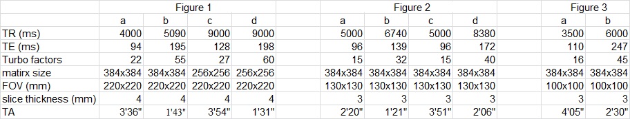
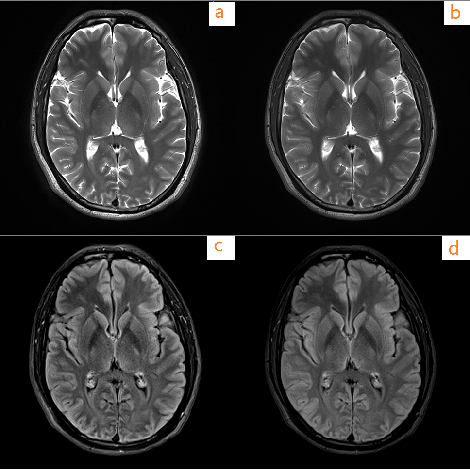
in vivo experiments were carried out by means of BLADE protocols with and without variable flip angle. All of measurements were achieved on a 3.0T MRI scanner (Spectra, SIEMENS Healthineers). Some imaging parameters are listed in Table 1. Experiment results are illustrated in Figure 1, Figure 2 and Figure 3. As shown in Figure 1, 2 and 3, image quality of BLADE with variable flip angle and enlarged width of strip is comparable with conventional BLADE. At the same time, the scan time was reduced in BLADE with VFL.
Conclusions
After T2 decay was mitigated via variable flip angle technique for BLADE, the efficiency of BLADE acquisition was improved as expected and the image quality is enough to clinical diagnosis. Generally speaking, the variable flip angles are smaller than constant flip angles in TSE. So the proposed method in this abstract will break thorough the SAR limits and the speed of BLADE can be increased further by reducing TR in some scenarios. Variable flip angle is an economical and efficient approach for speeding up BLADE scan.
Acknowledgements
No acknowledgement found.References
- Pipe JG. Motion correction with PROPELLER MRI: application to head motion and free-breathing cardiac imaging. Magn Reson Med 1999;42:963–969.
- Pipe JG, Zwart N. Turboprop: improved PROPELLER imaging. Magn Reson Med 2006;55:380–385.
- Hennig J, Weigel M, Scheffler K. Multiecho sequences with variable refocusing flip angles: optimization of signal behavior using smooth transitions between pseudo steady states (TRAPS). Magn Reson Med 2003;49:527–535.
- Hennig J, Weigel M, Scheffler K. Calculation of flip angles for echo trains with predefined amplitudes with the extended phase graph (EPG)-algorithm: principles and applications to hyperecho and TRAPS sequences. Magn Reson Med 2004;51:68–80.
Figures
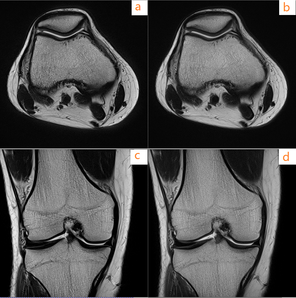
Knee images: (a) conventional T2 BLADE axial; (b) T2 BLADE with VFL axial; (c) conventional T2 BLADE coronal; (d) T2 BLADE with VFL coronal.