4231
Evaluating RF and gradient spoiling in MPRAGE and MP2RAGE using novel, efficient algorithms for 3D extended phase graph and ideal-spoiling models1Radiology, Perelman School of Medicine, University of Pennsylvania, Philadelphia, PA, United States
Synopsis
To optimize spoiling efficiency, we evaluate several design choices for RF- and gradient-spoiling in MPRAGE-type sequences. Optimization is performed using two efficient algorithms, one for the ideal-spoiling condition, and one for a 3D extended phase graph model that realistically captures spoiling effects. We used novel implementations of both algorithms, with publicly available source, that attempt to maximize computational efficiency. Our results suggest possible avenues for improving spoiling in MPRAGE-type sequences.
Introduction
MPRAGE1 and related sequences (e.g., MP2RAGE2, MPnRAGE3) T1 tissue contrast through the careful tuning of timing parameters and excitation flip angles. Almost all previous optimization work has used variations on an iterative solution of the Bloch equations to estimate the expected signal generated by different tissues under a variety of spoiling assumptions1-5. One exception is work by Kir and McMillan using a full extended phase graph (EPG) model to account for interactions between T1 relaxation and both gradient- and RF-spoiling6.
In this work we are interested in how to improve the spoiling of MPRAGE-type sequences, bringing them closer to the ideal-spoiling condition. We evaluate design decisions for gradient and RF spoiling, using novel, efficient algorithms for solving a) the steady state of any MPRAGE-type sequence in the ideal spoiling condition; and b) a full 3D EPG model with realistic spoiling behaviour.
Methods
Our ideal-spoiling algorithm recognizes that the steady state behaviour of the longitudinal magnetization during one TR of any MPRAGE-type sequence is the solution of a linear equation involving a matrix with zeros except for a unit diagonal, entries on the first sub-diagonal, and one additional entry in the top-right corner. This system is efficiently solved using the LU decomposition, and noting that the resulting U is atomic upper-triangular.
The 3D EPG is similar to previous implementations9, although unlike previous applications to MPRAGE6, we have included an isotropic diffusion model to account for these additional spoiling effects. Our algorithm uses a dynamically expanding representation of the 3D EPG state space to dynamically adapt to gradient spoiling directions of the sequence without prior information, and uses double-buffering of the state space to minimize memory allocation and copying.
Both the ideal-spoiling and 3D EPG simulations were written in C++, with an effort on maximizing computational efficiency, and their source is freely available7,8.
We simulated both MPRAGE and MP2RAGE sequences, with values of T1/T2 at 3 T for grey matter (GM), white matter (WM), and cerebral spinal fluid (CSF) used in previous optimizations2,5. Sequence parameters were chosen to match those previously suggested as optimal for MP2RAGE2, and the widely used Human Connectome protocol for MPRAGE these sequences using these tissue parameters11. (See Fig. 1 for tissue and sequence parameters).
For each sequence we performed a single ideal-spoiling simulation for each tissue. We then used 3D EPG simulations to explore several spoiling design decisions, with the goal of maximizing the similarity between 3D EPG output and the ideal-spoiling result. First, we considered both traditional 1D gradient spoiling, as is commonly used in MPRAGE-type sequences, and 3D hexagonal gradient spoiling, as recently demonstrated in FLASH10. We also varied the gradient spoiling moment between 1.5x ("low") and 5x ("high") the readout moment (5x chosen because this could be achieved with 80 mT/m gradients without modifying existing protocols). Finally, we varied the RF spoiling phase increment from 0° to 180° in increments of 0.5°. For each configuration of these options, we simulated 10 TRs of the sequence, and took the 10th TR as being in steady state.
Results
We are interested in what spoiling choices minimize the difference between the ideal-spoiling and 3D EPG output. Fig. 2 shows the 2-norm of the difference between the ideal-spoiling and 3D EPG results for MPRAGE at each choice of RF spoiling phase increment. Fig. 2a compares the effects of constant vs hexagonal gradient spoiling, and Fig 2b. compares the effects of low and high gradient spoiling.
Fig 3. shows similar results to Fig. 2, but for MP2RAGE.
Fig 4a. shows the evolution of the transverse magnetization over a single MPRAGE TR, using both the ideal-spoiling and EPG with both low and high hexagonal gradient spoiling and a 50° RF spoiling phase increment, as is commonly used in practice. Fig 4b. shows the evolution of the differences between the ideal spoiling signal and the two EPG signals.
Fig 5. shows similar results to Fig. 4, but for MP2RAGE.
Discussion
Figs. 2 and 3 suggest that, excluding a few high-error choices, it is difficult to discern an optimal choice of RF-spoiling phase increment. However, 3D hexagonal gradient spoiling significantly reduces error relative to constant gradient spoiling.
Figs. 4 and 5 demonstrate a small but notable improvement due to the use of high gradient spoiling moment. Further increasing spoiling moments will require longer echo spacing, requiring study on the tradeoff between fidelity and CNR/duration.
Our simulations suggest spoiling improvements for MPRAGE-typen sequences. Future work will include implementing these changes in the sequence software and validating simulation results with real phantom data.
Acknowledgements
Funding: NIH R00-HD074649, P30-NS045839, P41-EB015893, U01-HD087180.References
1. Mugler, John P., and James R. Brookeman. “Three-Dimensional Magnetization-Prepared Rapid Gradient-Echo Imaging (3D MP RAGE).” Magnetic Resonance in Medicine 15, no. 1 (July 1, 1990): 152–57.
2. Marques, José P., Tobias Kober, Gunnar Krueger, Wietske van der Zwaag, Pierre-François Van de Moortele, and Rolf Gruetter. “MP2RAGE, a Self Bias-Field Corrected Sequence for Improved Segmentation and T1-Mapping at High Field.” NeuroImage 49, no. 2 (January 2010): 1271–81.
3. Kecskemeti, Steven, Alexey Samsonov, Samuel A. Hurley, Douglas C. Dean, Aaron Field, and Andrew L. Alexander. “MPnRAGE: A Technique to Simultaneously Acquire Hundreds of Differently Contrasted MPRAGE Images with Applications to Quantitative T1 Mapping.” Magnetic Resonance in Medicine 75, no. 3 (March 1, 2016): 1040–53.
4. Deichmann, R., C.D. Good, O. Josephs, J. Ashburner, and R. Turner. “Optimization of 3-D MP-RAGE Sequences for Structural Brain Imaging.” NeuroImage 12, no. 1 (July 2000): 112–27.
5. van der Kouwe, André J. W., Thomas Benner, David H. Salat, and Bruce Fischl. “Brain Morphometry with Multiecho MPRAGE.” NeuroImage 40, no. 2 (April 1, 2008): 559–69.
6. Kir, Albert, and Alan McMillan. “Optimized Inversion-Prepared Gradient Echo Imaging.” Journal of Magnetic Resonance Imaging 36, no. 3 (September 2012): 748–55
7. https://github.com/mdtisdall/FLASHlikeSteadyState
8. https://github.com/mdtisdall/3DEPG
9. Weigel, Matthias. “Extended Phase Graphs: Dephasing, RF Pulses, and Echoes - Pure and Simple.” Journal of Magnetic Resonance Imaging 41, no. 2 (February 1, 2015): 266–95.
10. Hess, Aaron T., and Matthew D. Robson. “Hexagonal Gradient Scheme with RF Spoiling Improves Spoiling Performance for High-Flip-Angle Fast Gradient Echo Imaging.” Magnetic Resonance in Medicine, March 1, 2016.
11. http://protocols.humanconnectome.org/HCP/3T/imaging-protocols.html
Figures
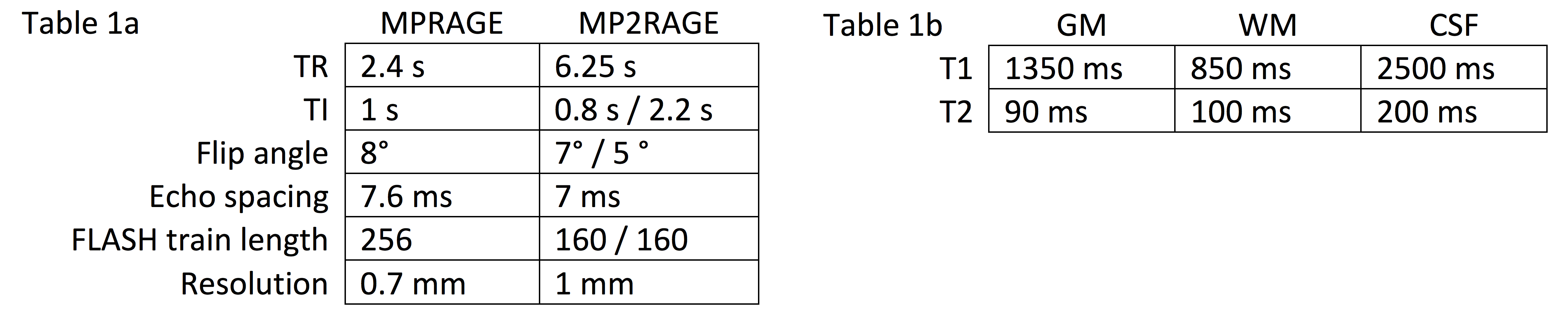
Table 1a gives the protocol parameters used for MPRAGE and MP2RAGE simulations.
Table 1b gives the tissue parameters used for grey matter (GM), white matter (WM), and cerebral spinal fluid (CSF) in both simulations.
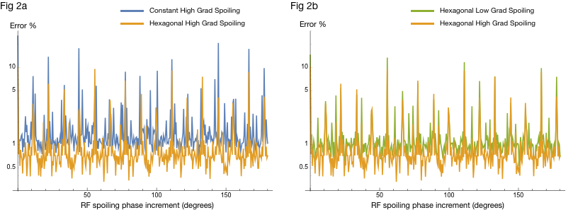
Fig 2. Log-plot of 2-norm error (across all samples in TR of all 3 tissues) of difference between MPRAGE EPG output and ideal-spoiling output. X-axes encode RF spoiling phase increment used for EPG simulation. Color indicates gradient spoiling choice for EPG simulation. Errors are scaled relative to the 2-norm of the ideal-spoiling signal, and so are expressed as a percentage of the "ideal" signal power. Lower percentage error indicates higher fidelity to the "ideal" signal.
Fig. 2a compares 1D constant and 3D hexagonal spoiling with "high" moments. Fig 2b compares 3D hexagonal spoiling with "high" and "low" moments.
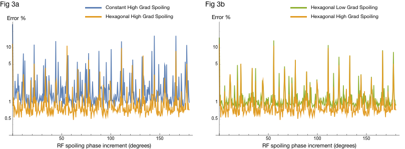
Fig 3. Log-plot of 2-norm error (across all samples in TR of all 3 tissues) of difference between MP2RAGE EPG output and ideal-spoiling output. X-axes encode RF spoiling phase increment used for EPG simulation. Color indicates gradient spoiling choice for EPG simulation. Errors are scaled relative to the 2-norm of the ideal-spoiling signal, and so are expressed as a percentage of the "ideal" signal power. Lower percentage error indicates higher fidelity to the "ideal" signal.
Fig. 3a compares 1D constant and 3D hexagonal spoiling with "high" moments. Fig 3b compares 3D hexagonal spoiling with "high" and "low" moments.
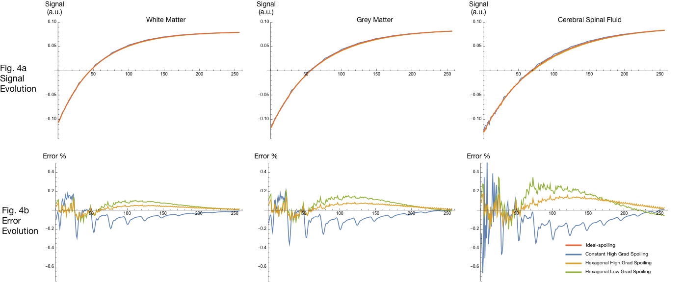
Fig 4. Plot of MPRAGE signal trajectories using 50° RF-spoiling increment, for GM, WM, and CSF (one per column). Color represents different spoiling configuration.
Fig. 4a shows the signal evolution during a single TR, with amplitude normalized to sum to unity. Note signals generally overlap when viewed at this scale.
Fig. 4b shows the evolution of the difference between the ideal-spoiling and the three EPG outputs. Errors at each time point are quantified as a percentage of the total ideal-spoiling signal amplitude.
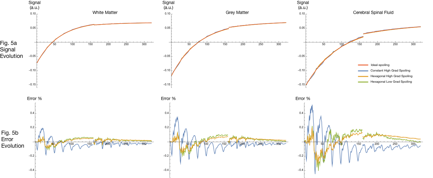
Fig 5. Plot of MP2RAGE signal trajectories using 50° RF-spoiling increment, for GM, WM, and CSF (one per column). Color represents different spoiling configuration.
Fig. 5a shows the signal evolution during a single TR, with amplitude normalized to sum to unity. Note signals generally overlap when viewed at this scale.
Fig. 5b shows the evolution of the difference between the ideal-spoiling and the three EPG outputs. Errors at each time point are quantified as a percentage of the total ideal-spoiling signal amplitude.