4228
Accelerated Spin Echo Imaging using Simultaneous Spin-Echo Refocusing in conjunction with a PINS Refocusing Pulse1Translational and Molecular Imaging Institute, Icahn School of Medicine at Mount Sinai, New York City, NY, United States
Synopsis
We proposed a novel alternative to the Turbo Spin Echo. It combines ideas from the Simultaneous Spin-Echo Refocusing method with PINS pulse design to result in a low SAR acquisition.
Introduction
Ultra-high field 2D Turbo Spin Echo (TSE) is hindered by high SAR and its sensitivity to transmit field (B1+) inhomogeneity. Reducing/modulating refocusing pulse angles (2,3), using adiabatic pulses (4), or applying parallel transmission (5) can mitigate these challenges. However, these strategies have drawbacks such as compromised image contrast, extended inter-echo spacing, or require specialist hardware.
Given the elevated SAR of TSE is due to the multiple high amplitude refocusing pulses, some methods have focused on using each to refocus multiple slices simultaneously, reducing the total number needed and hence lower SAR (6,7). The Simultaneous Spin-Echo Refocusing (SER) approach (6) excites multiple adjacent slices (offset in time and with unbalanced slice-rewind gradient moments) and uses slab-selective pulses for refocusing. However, the achievable reduction factor is limited by degraded slice profiles and the complicated spoiling scheme required to suppress spurious echoes. An alternative method replaces all excitation/refocusing pulses with PINS pulses (7), using parallel imaging to unfold aliased slices. However, the infinite extent of aliased slices imposes limits on the orientation of the acquisition.
In this work we demonstrate a novel sequence that combines SER with a PINS refocusing pulse, resulting in a method that is low SAR and can be acquired in any orientation.
Methods
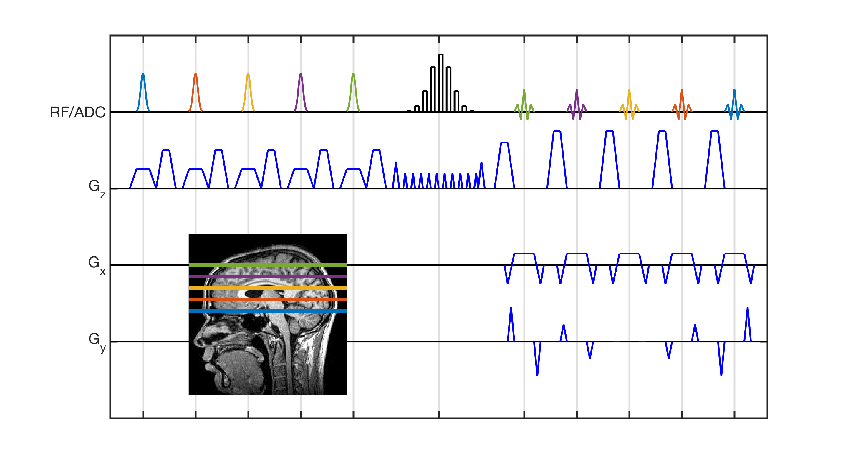
The sequence is shown in Figure 1. Multiple slices (the number of which is given by turbo factor, TF) are sequentially excited (pulse color indicates slice position), with slice-rewind gradients altered so that previously excited slices accrue a phase gradient. A single PINS pulse then refocuses all excited slices. The signal from each slice is measured when it forms a spin echo (each echo colored to indicate its slice), with gradients on the slice-axis unwinding the phase imparted by the modified slice-rewind gradients.
This kernel is nested in a repeating loop. The innermost loop repeats TF times, each iteration permuting the slice order so all slices acquire data for the current set of phase encode (PE) lines (i.e. Shot 1, slice order: 1,2,…,TF; Shot 2, slice order 2,3,…,TF,1; etc). This loop is repeated NPE/TF times (NPE = number of PE lines), to allow acquisition of all PE lines. The outermost loop enables acquisition of interleaved slices.
The sequence was implemented on a 7 Tesla whole-body scanner (Siemens, Magnetom) with a 1Tx32Rx coil (Nova Medical). Imaging was performed using a dual-compartment phantom (T1s=1917/830ms, T2s=1308/336ms) with the following parameters: TR=2s, TE=78ms, FOV=200mm, resolution=1.6mm2, inter-echo spacing=7ms, readout bandwidth=550Hz/pix, number of slices=9, TF=9, slice periodicity/width=20/5mm, scan time=4m50s. No parallel imaging was used; images were combined using sum-of-squares.
The sequence was implemented with an adiabatic refocusing pulse in order to demonstrate the SAR benefits of the proposed sequence. Excitation pulses were hyperbolic-secants (HS) (duration: 5ms, flip angle: 90°, BW: 2kHz, beta: 2.94). An adiabatic single-band HS refocusing pulse was designed based on condition III of Park & Garwood (8) (duration: 5ms, BW: 2kHz, beta: 5.88) to ensure the through-slice quadratic phase imparted by the excitation is refocused. This was used as an envelope for the PINS pulse (9), which was created by sub-sampling the single-band waveform with 40 sub-pulses of 0.1ms duration, interleaved with gradient blips to achieve the correct slice periodicity. Modified slice-rewind gradients and refocusing pulse crushers imparted 10π across each slice. The Siemens UHF-TSE (WIP729) with matched protocol parameters was used for comparison.
Results
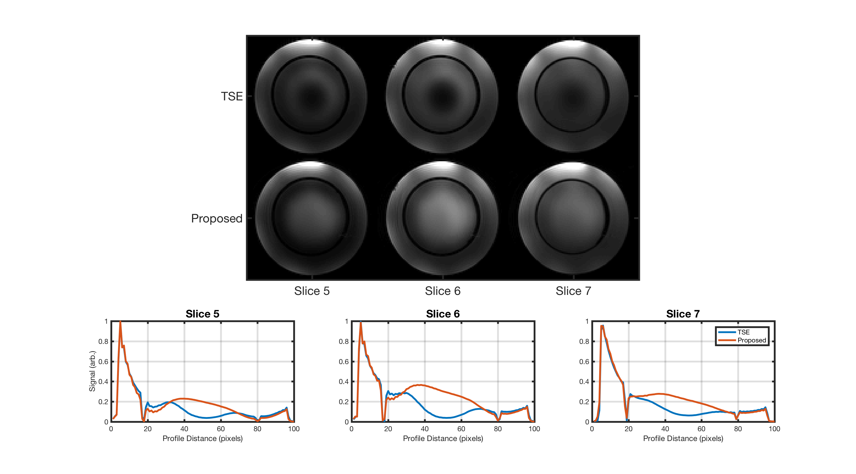
Figure 2a shows images from three example slices acquired with both the standard TSE (top) and proposed sequence (bottom). Both faithfully depict the object, although the proposed technique does not suffer from localized reduced signal due to B1+ inhomogeneity. Note the proposed sequence has low-level residuals artifact due to minor phase consistencies between adjacent segments of k-space. Figure 2b shows vertical signal profiles through each slice, depicting the signal recovery due to the adiabaticity of the refocusing pulse.
Of note is the SAR reduction offered by the proposed sequence; a standard TSE comprised of the HS excitation and TF single-band HS refocusing pulses would have a SAR level 350% of the proposed sequence.
Discussion
We have demonstrated a new pulse sequence to acquire spin echo images with reduced SAR as compared to standard TSE. Its structure is based upon the SER sequence, but the use of an adiabatic PINS refocusing pulse enables greater slice-acceleration factors to be achieved while maintaining insensitivity to B1+ inhomogeneity. The sequence is similar to sequences such as SPEN and RASER (10,11). However, the frequency sweep pulses are replaced with discrete excitation pulses. Further work will explore making the excitation pulses multiband in addition to further exploring the SAR benefits of the proposed technique.Acknowledgements
This work was funded by NIH R01 CA202911-01A1, the NARSAD Young Investigator Grant, Mount Sinai Hospital Seed Funds and Icahn School of Medicine Capital Campaign.References
1. Hennig J et al, MRM (1986) 3:823
2. Hennig J, JMR (1988) 78:397
3. Hennig J et al, MRM (2003) 49:527
4. Van Kalleveen IML et al, MRM (2012) 68:580
5. Sbrizzi A et al, MRM (2017) 77:361
6. Gunther & Feinberg, MRM (2005) 54:513
7. Norris DG et al, MRM (2014) 71:44
8. Park JY & Garwood M, MRM (2005) 54:513
9. Koopmans PJ et al, MRM (2013) 68:1670
10. Chamberlain R et al, MRM (2007) 58:794
11. Tal A & Frydman L, Prog. Nucl. Magn. Res. Spect. (2010) 57:241
Figures