4225
Inversion-Recovery UTE multispoke sequence: comparison of two excitation schemes1Université de Strasbourg, CNRS, ICube, FMTS, Strasbourg, France, 2Institut Mines Télécom Atlantique, INSERM, LaTIM, Brest, France
Synopsis
Inversion-Recovery UTE sequences have been used to highlight and quantify short-T2 structures. Covering a 3D volume remains time-consuming, and a trade-off often needs to be found between k-space undersampling and acceptable appearing streaking artifacts. As such, acquiring several radial spokes within a single repetition time represents a supplementary sequence acceleration possibility. In this work, we propose to quantify the short-T2 signal difference between a constant and an optimized variable flip angle strategy in a multispoke acquisition module, and within a long-T2 suppression condition in vitro.
Introduction
Inversion-Recovery UTE (IR-UTE) sequences demonstrated efficiency for short-T2 structures characterization1,2. Unfortunately, a 3D-covered acquisition often requires prohibitively long scan times. K-space undersampling may be considered to reduce the latter, although at the cost of appearing streaking artifacts on the reconstructed image.
Acquisition of several spokes within a single TR was previously proposed to provide sequence acceleration3,4. The variable flip angle (VFA) excitation scheme presented in Ref. 5 was primarily employed to reduce signal variations and to maximize the short-T2 component's signal through the consecutive pulses. Nevertheless, the resulting averaging of the center-out acquisition pattern in UTE sequences lower the effects of such variability on the resulting image in the case of a constant flip angle scheme (CFA).
In this work, we propose to quantify the gain in terms of short-T2 signal between VFA and CFA excitation schemes in an IR-UTE multispoke (IR-UTE-MS) sequence in vitro, and within long-T2 suppression condition.
Methods
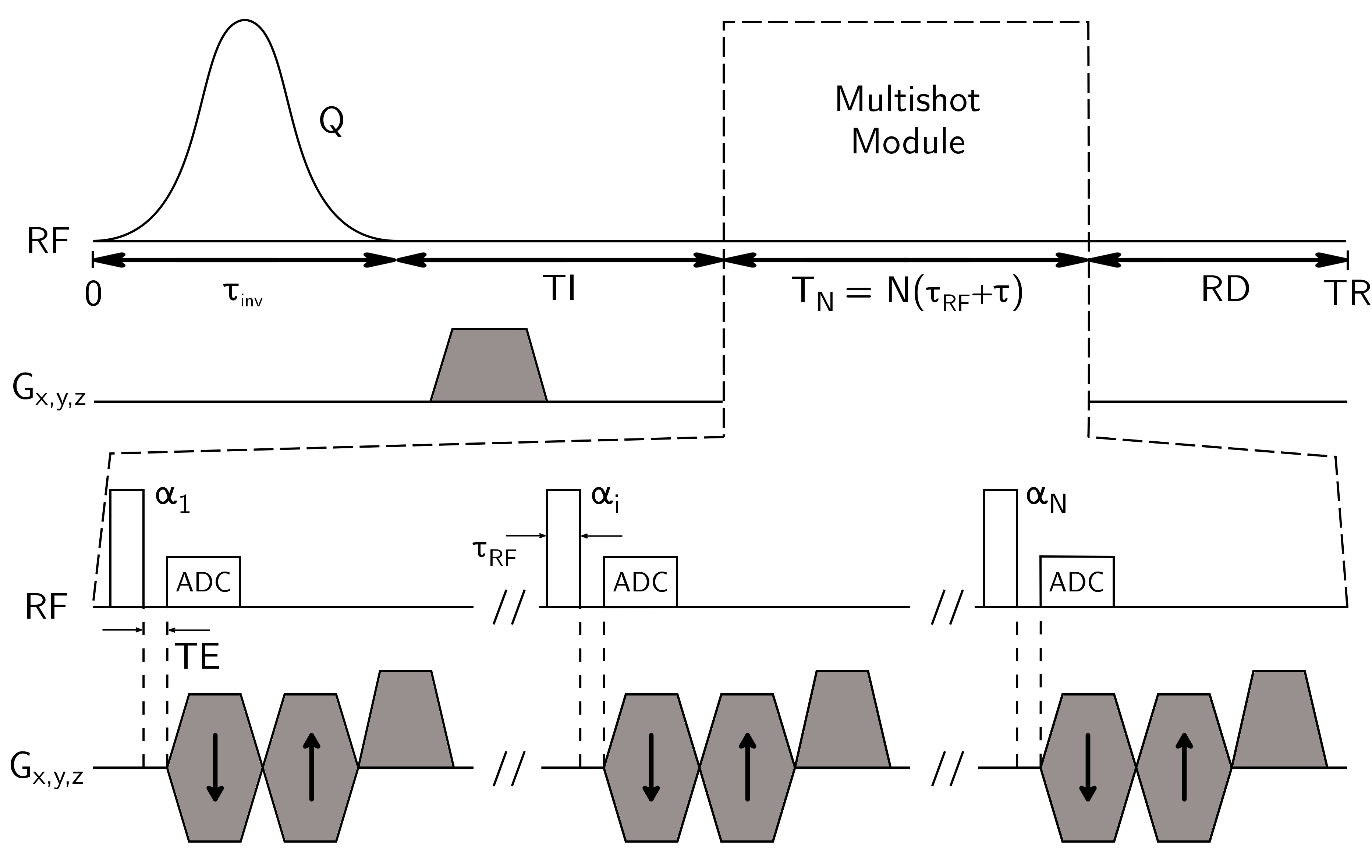
The IR-UTE-MS pulse sequence is described in Figure 1. In the following, the superscripts $$$^L$$$ and $$$^S$$$ will indicate the long and short-T2 component, respectively.
The general equation tracking a perfectly spoiled longitudinal magnetization prior to each excitation pulses is given using the Bloch equations:
$$M_{z,k}^-=M_{z,1}^{-}E_\tau^{k-1}\displaystyle\prod_{p=1}^{k-1} f_{z,p}+M_0(1-E_\tau)\sum_{i=1}^{k-1}E_\tau^{i-1}A_i$$
with $$$A_1=1$$$, and $$$A_i=\prod_{p=k+1-i}^{k-1}f_{z,p}$$$ otherwise, $$$M_{z,k}^{-}$$$ longitudinal magnetization prior to the k-th pulse, and:
$$M_{z,1}^{-}=M_0\frac{(1-E_I)+E_I(1-E_{RD}E_\tau)Q+QE_IE_{RD}(1-E_\tau)\displaystyle\sum_{i=1}^{N-1}E_\tau^{i}\displaystyle\prod_{p=N+1-i}^{N}f_{z,p}}{1-QE_IE_{RD}E_\tau^{N}\displaystyle\prod_{p=1}^{N}f_{z,p}}$$
where $$$M_0$$$ is the magnetization amplitude at thermal equilibrium, Q the inversion efficiency, $$$\{E_I/E_\tau/E_{RD}\}=\{e^{-TI/T_1}/e^{-\tau/T_1}/e^{-RD/T_1}\}$$$, T1/T2 longitudinal and transverse relaxation times, $$$TI$$$ inversion delay, RD resting delay before TR, $$$f_z$$$ longitudinal mapping function taking into account relaxation occurring during excitations (pulses duration $$$\tau_{RF}$$$)6, and N the number of spokes acquired in a single TR.
A minimization of the long-T2 signal has been proposed by solving the following4:
$$\hat{TI}=\text{argmin}_{TI}\left(\sum_{k=1}^N M_{z,k}^{-,L}\sin(\alpha_k)\right)=\text{argmin}_{TI}\left(\sum_{k=1}^N M_{xy,k}^L\right)$$
with $$$M_{xy,k}^L$$$ the k-th long-T2 transverse magnetization after its corresponding excitation.This process relies on the strong assumption of a perfectly spoiled magnetization between the consecutive excitations, which is invalid for long-T2 components given the short intershot delay $$$\tau$$$ ($$$<T_2^L$$$). In addition, the appropriate RF spoiling scheme to yield the same $$$M_{xy,k}^L$$$ quantities from the optimized solution is not trivial. As a consequence, the long-T2 signal is simulated using a configuration states framework7 with a null RF phase for every pulse, and the optimal $$$TI$$$ iteratively estimated.
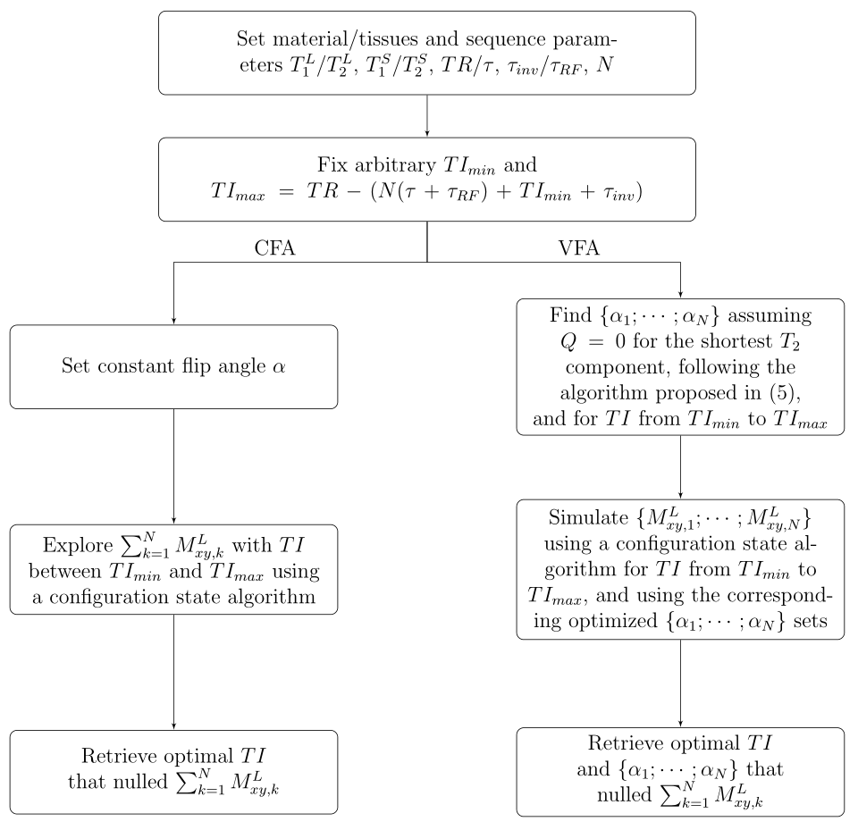
A pipeline for parameters selection for both VFA and CFA schemes is presented in Figure 2.The consecutive flip angles in VFA were computed using the method proposed in Ref. 5, assuming a saturation of the short-T2 component through the inversion process (Q=0) and prior knowledge of $$$T_1^S/T_2^S$$$.
To quantify the short-T2 signal gain between both excitation schemes, we defined:
$$R=\frac{\sum_{k=1}^{N}M_{xy,k}^{VFA,S}-\sum_{k=1}^{N}M_{xy,k}^{CFA,S}}{\sum_{k=1}^{N}M_{xy,k}^{CFA,S}}$$
with:
$$M_{xy,k}=M_{z,k}^-f_{xy,k}$$
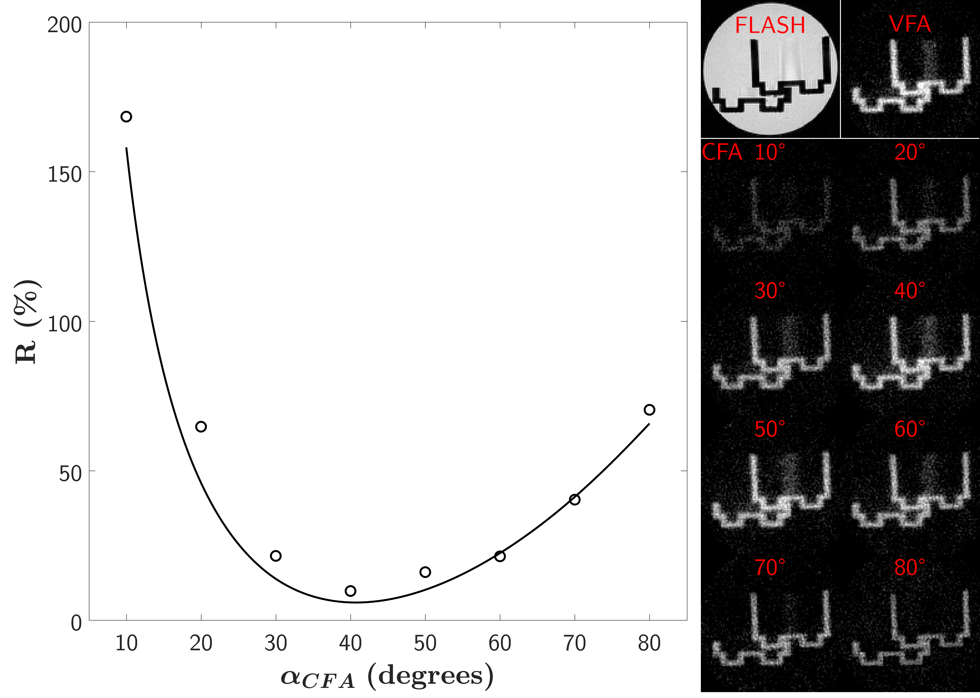
where $$$f_{xy,k}$$$ is the transverse mapping function associated to the k-th pulse6. A phantom composed of Lego bricks ($$$T_1^S/T_2^S$$$≈300/0.2 ms8) soaked into a doped water (1.5%-agarose/0.5 mM Ni2+; $$$T_1^L/T_2^L$$$=1400/70 ms) was scanned using a 7T preclinical scanner (Bruker BioSpec, Ettlingen, Germany) with a 72-mm Tx/Rx volume coil. In simulations and experiments, the sequence parameters were: TR/TE=200/0.01 ms, N=5, $$$\tau$$$=5 ms, $$$\tau_{RF}$$$=0.05 ms, first-order 5-kHz sech inversion pulse with $$$\tau_{inv}$$$=15.57 ms, matrix size 128x128x128, voxels size 250x250x500 μm3, receiver bandwidth of 150 kHz, 34087 spokes and 4 accumulations (Tacq/scan=1h31). Specific parameters were constant $$$\alpha_{CFA}$$$=10/20/30/40/50/60/70/80° with respective $$$TI$$$=79.5/76.3/75.5/74.0/72.1/70.5/69.3/68.3 ms for CFA experiments, and $$$\{\alpha_1;\cdots;\alpha_5\}$$$={29.8;33.3;38.6;48.1;90.0°} with $$$TI$$$=69.5 ms for the VFA one. Mean signals from a ROI drawn in the Lego brick were used to compute the $$$R$$$ ratio. An additional 3D-FLASH acquisition was performed for comparison purpose: TR/TE=30/3 ms, $$$\alpha$$$=20°, and same matrix and voxels size.
Results
Figure 3 shows simulation and experimental results of the $$$R$$$ ratio, along with views of the imaged phantom. An expected higher short-T2 signal was generated using the VFA scheme in the Lego brick under a long-T2 suppression condition along the various CFA flip angles, with a minimal gain of 9.8% for $$$\alpha_{CFA}$$$=40°.Conclusion
In the present work, the VFA scheme systematically yielded a higher signal in the short-T2 material compared to the CFA strategy. The difference between simulated and experimental $$$R$$$ ratio is attributed to deviations about prior values of relaxing and inversion efficiency parameters of the short-T2 material. In addition, the VFA strategy was presented given a maximum flip angle of 90°, which consequently increases the maximal expected short-T2 signal. Although even more signal might be generated in VFA given exact $$$T_1^S$$$, $$$T_2^S$$$ and Q values, the CFA strategy remains easier to implement on scanners. Furthermore, it does not require high flip angles nor priors about relaxing parameters of the component of interest to generate a suitable short-T2 signal in a suppressed long-T2 condition.Acknowledgements
No acknowledgement found.References
1. Horch RA, Gochberg DF, Nyman JS, Does MD. Clinically compatible MRI strategies for discriminating bound and pore water in cortical bone. Magnetic Resonance in Medicine 2012;68:1774–1784
2. Du J, Ma G, Li S, Carl M, Szeverenyi NM, VandenBerg S, Corey-Bloom J, Bydder GM. Ultrashort echo time (UTE) magnetic resonance imaging of the short T2 components in white matter of the brain using a clinical 3T scanner. NeuroImage 2014;87:32–41
3. Carl M, Bydder GM, Du J. UTE imaging with simultaneous water and fat signal suppression using a time-efficient multispoke inversion recovery pulse sequence. Magnetic Resonance in Medicine 2016;76:577–582
4. Ma YJ, Chang EY, Carl M, Du J. Quantitative magnetization transfer ultrashort echo time imaging using a time-efficient 3D multispoke Cones sequence. Magnetic Resonance in Medicine 2017;00:1–9
5. Li C, Magland JF, Zhao X, Seifert AC, Wehrli FW. Selective in vivo bone imaging with long-T2 suppressed PETRA MRI. Magnetic Resonance in Medicine 2017;77:989–997
6. Sussman MS, Pauly JM, Wright GA. Design of practical T2-selective RF excitation (TELEX) pulses. Magnetic Resonance in Medicine 1998;40:890–899
7. Weigel M. Extended phase graphs: Dephasing, RF pulses, and echoes - pure and simple. Journal of Magnetic Resonance Imaging 2015;41:266–295
8. Codd S, Mallett M, Halse M, Strange J, Vennart W, Doorn T. A Three-Dimensional NMR Imaging Scheme Utilizing Doubly Resonant Gradient Coils. Journal of Magnetic Resonance, Series B 1996;113:214–221
Figures