4201
Initial Investigation of Multi-Probe Magnetic Field Monitoring on a Whole-Body Human System Operating at 10.5 Tesla: Application to Spin Echo Diffusion Weighted EPI1Center for Magnetic Resonance Research, University of Minnesota, Minneapolis, MN, United States
Synopsis
DW-EPI is subjected to image distortion induced by eddy currents. Magnetic field camera has been shown to provide corrected reconstruction based on accurate measurement of actual k-space trajectories. In this study, initial effort was made to implement this approach in the context of a whole body human system operating at 10.5T where susceptibility challenges are greater. After characterization of the probe behavior and careful design of the probe signal acquisition scheme, field evolution during the EPI readout was mapped. Image reconstruction corrected with the measured encoding information demonstrated a significant reduction of image distortion in DW-EPI.
Introduction
Diffusion weighted imaging (DWI) with EPI readout is sensitive to diffusion gradient induced eddy currents, resulting in image shift and distortions. At ultrahigh field, shorter tissue T2 calls for shortest possible TE, implying maximizing diffusion gradient strength and slew rate1, thus larger eddy currents. It has been shown that magnetic field monitoring2,3 can accurately trace k-space trajectories and field fluctuations4,5, providing the means to reconstruct correct images. To our knowledge, this technique had not been applied at 10.5T, which implies larger susceptibility induced challenges. Here, we aimed at identifying potential constraints that may arise at 10.5T to successfully deploy a multi-probe magnetic field camera and we evaluate the approach with a diffusion weighted EPI sequence.Methods
Experiments were conducted on a 10.5T whole body scanner (Siemens Healthcare, Erlangen, Germany).
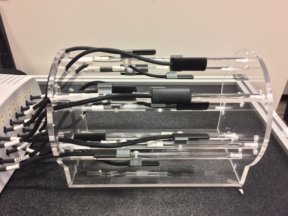
Camera setting: our center was recently equipped with a 16 (19F) probes clip-on magnetic field camera (Skope, Zurich, CH), with one set of 7T probes and one set of 10.5T probes. For measurements, the probes are distributed on a plastic scaffold positioned at the magnet iso-center.
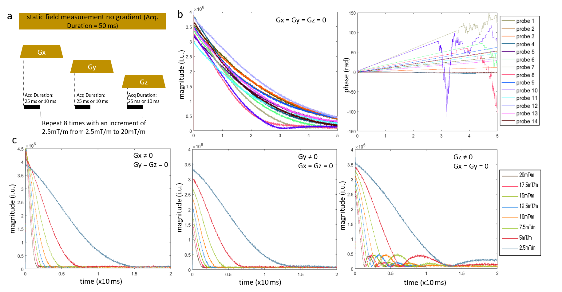
Probes: an initial qualitative comparison of the free induction signal decay during the first 10ms of signal readout was made at 7T and 10.5T in the absence of applied gradient. Further measurements were pursued at 10.5T, comparing the lifetime of the signal in the absence with or without a constant gradient applied on one axis (Fig.1a). This information was later used to optimize probe excitation/readout events (e.g. interleaves) during when measuring MR sequences. For our diffusion protocol, at any time during the EPI train of echoes, the probe signal could be read up to 14ms after probe excitation.
Phantom experiments were obtained with an eight channel transceiver array head coil6,7 loaded with a spherical oil phantom (ø=16cm). A 2D, monopolar DWI Spin Echo sequence was used with following parameters: encoding (bvalue=2000s/mm2) applied in six standard orientations, plus one reference with bvalue=0, TR/TE =7000/109ms, resolution=2.40x2.40x1.05mm3, bandwidth=1352Hz/px, echospacing=0.8ms. In this initial stage no imaging acceleration was used to avoid confounding factors during image reconstruction.
Retrospective correction: the actual k-space coordinates of signal sampling during the DWI-SE-EPI readout were calculated by combining the measured field evolution with the known dwell time of the DW-EPI sequence. After acquisition with the oil phantom, original raw data (k-space) were transferred to another server. Image reconstruction based on measured k-space trajectories (kx,ky) was performed similarly to that described by ref 5, using a 2D non-uniform fast Fourier Transform algorithm8 . The reconstruction was programmed in Matlab. A direct 2D Fourier transform of the original kspace measured by the scanner, followed by a 3-reference line Nyquist ghost correction9, was conducted as a control. Edge detection was performed to facilitate the comparison between the two reconstructions.
Results
The mean (+/-sd) relative signal decrease over 10ms for the probes in static field without gradient at 7T and 10.5T was 23.5%±2.8% and 34.7%±5.6%, respectively. Without gradient, the time during which the probes provide signal with decent quality approached 25ms (see signal magnitude and phase, Fig.1b). When a gradient was applied, as expected, signal decay was faster as the gradient strength increased (Fig.1c). This effect was not homogeneous through axes: in the presence of Gz, instead of a monotonic decay, a signal rebound was observed after a first trough. This was attributed to local susceptibility within the probe structures, with constructive and destructive interferences between probe isochromats.
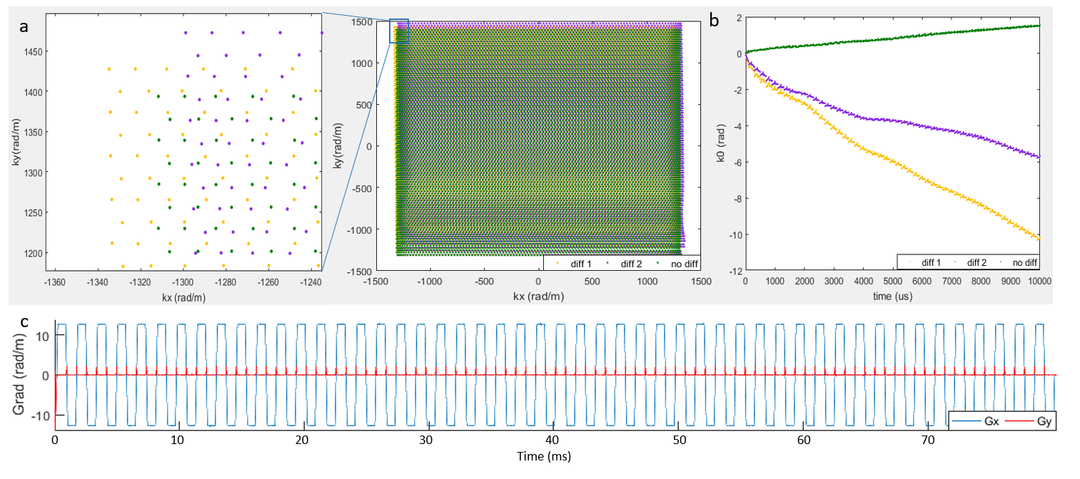
When monitoring the field trajectories during the diffusion SE EPI sequence, the measured kx, ky and k0 trajectories were clearly differently altered by different diffusion encoding directions, as illustrated in Fig.3 for two directions. The corresponding readout and phase encoding gradient applied during the EPI readout, calculated as the derivative of kx and ky, are shown in Fig.3c.
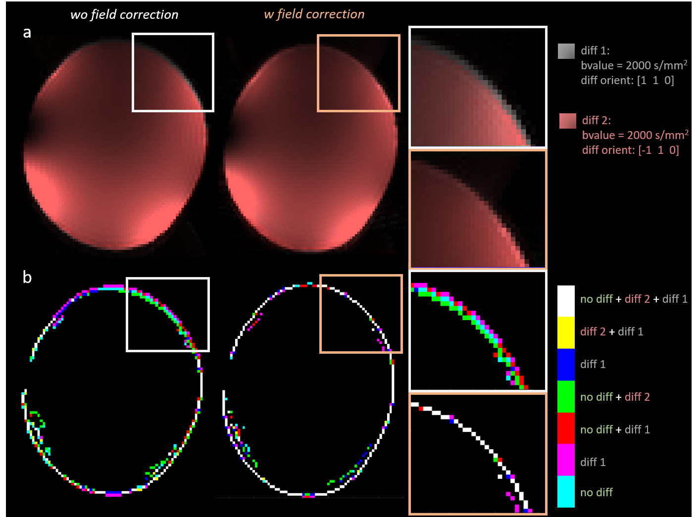
In the image domain, variable image distortions (sheer, shrinkage, dilation) were easily identified for different diffusion directions. A comparison between image reconstruction obtained with and without correction for trajectory deviations is displayed in Fig.4. As can be seen, image differences between two different diffusion weights were considerably reduced when reconstructing the images based on the measured trajectories.
Conclusion and discussion
Despite a shorter lifetime of probe signals at higher field and a non-monotonic decay in the presence of Gz (attributed to susceptibility effects2), successful correction for k-space deviations during image reconstruction was obtained at 10.5T using a DWI-SE-EPI sequence. It should be mentioned that full k0 control will require further efforts to account for real-time B0 modulation applied by the RF synthesizer of the scanner to mitigate B0 eddy currents.Acknowledgements
The authors would like to give thanks to Andrea Grant for the initial set up of the study and Gregor Adriany for providing guidance in RF coil usage during the acquisition.
Supporting grant: S10 RR029672 “Console for 10.5 Tesla Whole Body MRI System”
References
1, Gallichan D. Diffusion MRI of the human brain at ultra-high field (UHF): A review. Neuroimage. 2017;(xxxx). doi:10.1016/j.neuroimage.2017.04.037.
2, De Zanche N, Barmet C, Nordmeyer-Massner JA, Pruessmann KP. NMR Probes for measuring magnetic fields and field dynamics in MR systems. Magn Reson Med. 2008;60(1):176-186. doi:10.1002/mrm.21624.
3, Barmet C, De Zanche N, Pruessmann KP. Spatiotemporal magnetic field monitoring for MR. Magn Reson Med. 2008;60(1):187-197. doi:10.1002/mrm.21603.
4, Wilm BJ, Nagy Z, Barmet C, et al. Diffusion MRI with concurrent magnetic field monitoring. Magn Reson Med. 2015;74(4):925-933. doi:10.1002/mrm.25827.
5, Kasper L, Bollmann S, Vannesjo SJ, et al. Monitoring, analysis, and correction of magnetic field fluctuations in echo planar imaging time series. Magn Reson Med. 2015;74(2):396-409. doi:10.1002/mrm.25407.
6, Gregor Adriany G, Lance DelaBarre L, Eryaman Y, et al. Initial imaging results with a 10.5T geometrically adjustable dipole array. 2016 Workshop on Ultra High Field MRI: Technological Advances & Clinical Applications
7, Ertürk MA, Wu X, Eryaman Y, et al. Toward imaging the body at 10.5 tesla. Magn Reson Med. 2017;77(1):434-443. doi:10.1002/mrm.26487.
8, Greengard L, Lee J-Y. Accelerating the Nonuniform Fast Fourier Transform. SIAM Rev. 2004;46(3):443-454. doi:10.1137/S003614450343200X.
9, Heid O. Robust EPI phase correction. Proceedings of the 5th Annual Meeting of ISMRM, Vancouver, Canada, 1997(Abstract 2014)
Figures