4185
Comparison of electromagnetic and thermal simulations with measurements of different orthopedic implants system at 1.5T1MR:comp GmbH Service for MR Safety & Compatibility, Gelsenkirchen, Germany, 2MRI-STaR-Magnetic Resonance Institute for Safety,Technology and Research GmbH, Gelsenkirchen, Germany
Synopsis
With aid of the numerical simulations the test of a typical commercial orthopedic implant system composed of huge amount of multi-component implants varying in dimensions or materials is doable in realistic time and cost regarding the radio frequency induced heating. Electromagnetic and thermal simulations are applied to confirm the worst case configuration, locate the hotpot and interpret the temperature rise which is compared with the experiment test. To catch the worst case scenario the placement of the test object should be considered in relation to the local electrical field and the setup of simulation should approach the experimental condition.
Introduction
Radio frequency- (RF-) induced heating is one of the most critical risks in MRI scanning of medical implants. To avoid those risks medical implants must be tested according to ASTM standard F2182-11a in an MR environment, where numerical simulations including electromagnetic (EM) and thermal simulations are employed to select the potential worst case configuration from the whole implant system under test which will be later on measured in experiment.
We present here the comparison between EM and thermal simulations [2,3,4] as well as measurement of commercial orthopedic implants to discuss the critical parameters in simulations and analyze the results between simulation and measurement from a commercial point of view.
Content
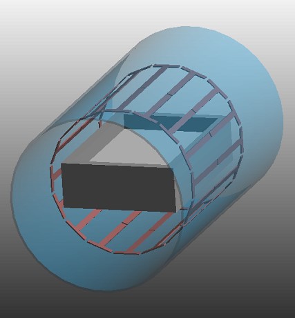
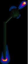
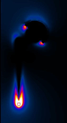
METHODS: The numerical analysis involved full-wave 3D EM computer simulations followed by corresponding thermal simulations. The simulations were carried out with the SEMCAD X V14 (Schmid & Partner Engineering AG, Zürich, Switzerland) finite-difference time-domain (FDTD) simulation platform and the thermal solver in CST studio suite 2017 (CST, Darmstadt, Germany). Initially the ASTM phantom container (65 cm x 42 cm x 14 cm) filled with the tissue simulating gel of 9 cm depth was placed inside the coil at the position where the center of the gel was located at the isocenter, see figure 1. The fully immersed test object is generally placed along the side phantom wall so that the longitudinal structure of the test object is aligned with the tangential electrical field. The test object might be shifted in order to make sure that the whole test object and especially the hotspot position is placed in the strongest background electrical field. The 0.1 g averaged SAR and the corresponding temperature rises were calculated from simulations to evaluate different configurations of the implants regarding the heating issue, see figures 2 & 3. The physical RF-induced heating tests were performed according to current ASTM standard F2182-11a using the RF fields of commercial MR scanners of different vendors and different field strengths as well as the Medical Implant Test System MITS 1.5 (Zurich MedTech, Switzerland). Three temperature probes have been placed at the implant where the RF heating is expected to be the largest determined in a computer simulation or by laboratory experience.
RESULTS: In most cases EM simulations already find worst case test objects and hotspots at correct (validated by thermal simulations) positions, therefore this procedure are often requested by orthopedic implant manufacturers in order to save budget. The SAR evaluation is more sensitive in presenting the small changes of the configurations while the temperature is mainly affected by the material properties defined in the thermal simulations. To test the sensitivity of the different components, EM simulation gives opportunity to magnify the impact of each component while the thermal simulations validate the analysis and avoid the unexpected overestimation. The exact location of the test object has to be investigated. Besides the most critical factor of the tangential background electrical field the specific contracture of the implant needs to be also analyzed. For example: the orientation of the screws or the long implant exceeding the homogenous background electrical field area. Furthermore, thermal simulation and measurements show good agreement with the difference less than 10 % at the hotspot.
DISCUSSION: This work discusses the RF-induced heating on commercial orthopedic implants for simulated and measured data as well as the influence of setup parameters and test object parameters under the aspect of limited simulations as requested by most orthopedic implant manufacturers. While thermal simulation [2,3,4] provide precise hotspot location at submillimeter scale, this comparison shows that reduced simulation effort with even EM simulations only found correct worst case test object and hotspot for most implant systems.
CONCLUSION: Both EM and thermal simulation offer complete observation in study of the RF induced heating caused by different configurations for most commercial orthopedic implant systems. Due to the individual structure of the test object, the location of the test object and the phantom needs to be discussed to detect the worst case scenario. Validation and uncertainty analysis for both numerical simulations and measurement are necessary for further study.
Acknowledgements
No acknowledgement found.References
1. Wolfgang Görtz, Nicolas Fülle, Gerrit Schönwald, Susanne Matthey, and Gregor Schaefers. RF-Heating Testing in 64 MHz RF-Laboratory System and 1.5 Tesla MRI – a Comparative Evaluation. ISMRM 2013 no. 2826.
2. Mahdi Abbasi, Yacine Noureddine, Gregor Schaefers, and Daniel Erni. Uncertainty of RF Induced Heating Tests of a Generic Orthopedic Implant in Different Phantoms. ISMRM 2016 no. 3644.
3. M. Kozlov, G. Schaefers. Comprehensive analysis of temperature rise generated by a titanium rod inside 1.5T MRI RF whole body coil. ISMRM 2015.
4. Mikhail Kozlov, Gregor Schaefers. Investigation of RF-induced heating of distal radius implant system. ISMRM 2017 no. 2630.
Figures