4174
Platform for investigating spatial and intensity parameters for phase-sensitive MRI focal localization with steerable single element focused ultrasound transducers through skull1Department of Radiology, Brigham and Women's Hospital, Harvard Medical School, Boston, MA, United States
Synopsis
A platform is designed and constructed for investigating Focused Ultrasound (FUS) spatial and intensity focal parameters during phase-sensitive MRI focal localization. Recently, there has been a large interest to use single element transducers to deliver therapy to the brain. Spatial accuracy and intensity safety limits need further investigation. The platform developed in this project uses 3D Slicer software to incorporate MRI and neuronavigation camera coordinates for guiding an automated 3D hydrophone mapping system. A 272 kHz single element FUS transducer, ex vivo skull, and gel phantom are used to demonstrate components of the integrated MRI and navigation based hydrophone mapping system.
Introduction
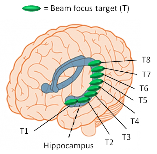
Focused Ultrasound (FUS) has become of great interest as a perspective treatment for neurological disorders. The most recent success is shown in high-intensity FUS ablation for thalamotomy in Essential Tremor patients.1 These procedures use a hemispherical phased array transducer with multiple elements, which use real-time MR-Thermometry (MRT) to monitor ablation and track ultrasound beam steering in the brain. However, others have investigated using single element FUS transducers with a lower geometric gain to deliver nondestructive tissue intensities to the brain for functional brain mapping, drug delivery, and for repeated ultrasound exposure applications. With these exposures, it will likely not be possible to produce a measureable temperature rise in order to guide the FUS beam target with MRT.2 The use of single element devices may offer a more economic advantage compared to phased arrays. Some investigations have had success in using MRI based neuronavigation systems and patient specific computer finite element modeling to estimate the FUS beam position and intensity for an individual target location.3,4 One major issue in the use of FUS single element transducers is the uncertainty in focal positioning and intensity when passing through the different areas of the skull, especially when multiple target locations are desired (example in Fig. 1) and limits their use for brain therapy.Methods
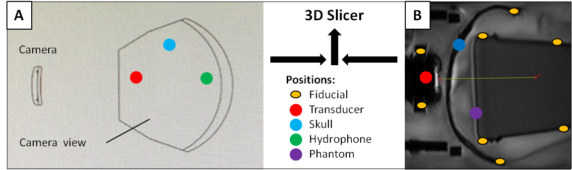
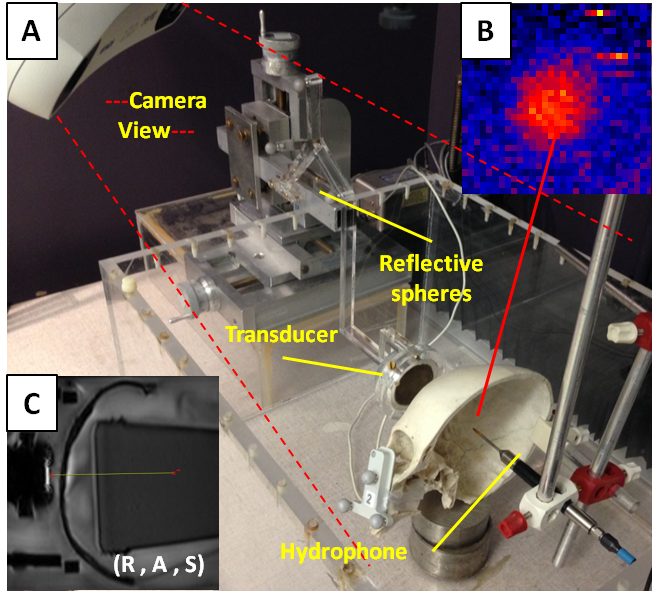
An MR-Elastography (MRE) pulse sequence, which is an MRI phase-sensitive imaging method, was synchronized with FUS Acoustic Radiation Force (ARF) pushing using a motion encoding gradient frequency of 50 Hz. This was used in attempt to image a focal area when a single element transducer transmitted an ARF push through an ex vivo human skull at the temporal window. The FUS transducer (220 kHz, 5 cm diameter, F# = 2) was mounted in a steerable MR-compatible housing and placed in front of the skull within water tank. The tank was placed in a GE 3T MRI head coil for imaging. A cylindrical gel phantom with viscoelastic parameters similar to soft tissue is used as the targeting area inside the skull. Pointer tool registration is used for linking fiducial positions and reflective sphere patterns mounted to reference points on the transducer, skull, phantom, and hydrophone positing system. The transducer relative to the skull and phantom MRI positions are reestablished via neuronavigation in the bench top water tank for hydrophone mapping (Fig. 2). Both navigation camera and the MRI coordinate systems are integrated via 3d Slicer5 (workflow shown in Fig. 3). The phantom MRI image volume is overlaid back into the skull as it was positioned during MRI scanning. An automated 3D hydrophone scanner maps the FUS intensity within the skull relative to MRI coordinates of the projected phantom as shown in Fig 3(B) and can be compared to any focal regions obtained during the phase-sensitive MRI.3,4Results
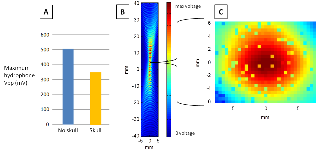
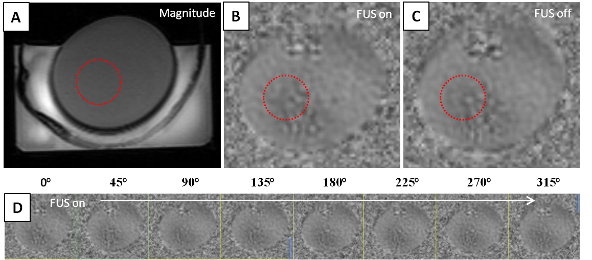
There is approximately a 30% loss in FUS intensity found from hydrophone mapping when transmitted through the center portion of the temporal widow in our human ex vivo (Fig. 4) skull and is in agreement with a previous study.6 The results from scanning a gel phantom with MRE in synchronization with ARF pushing are shown in Fig. 5. FUS is turned on during one scan and turned off during a repeated scan.Discussion and Conclusion
We have designed and constructed a platform for investigating FUS spatial and intensity parameters during phase-sensitive MRI focal localization. There appears to be little or no displacement seen in our preliminary MRE scanning from ARF pushing when visually analyzing the difference between Fig 5(A) and Fig 5(B). However, there has been success from other studies using motion encoding gradients from MRE pulse sequences to image FUS ARF pushes.7 Our next step is to use a single cycle motion encoding gradient MR-ARF pulse sequence to image the FUS focus8 and also to further isolate MRI motion artifact stemming from image gradient vibrations during scanning. Once we obtain a focal location from MRI in the phantom, we will verify the MRI spatial location with the navigation based hydrophone mapping and analyze the FUS intensity. The platform developed will help gain insight on how FUS intensities required to create an MRI visible ARF push in specific brain regions compare with intensity limits found to be safe in recent human studies using single element transducers.3,4 This platform allows multiple targeting points of interest to be investigated (as in the example scenario of Fig. 1 for the left hippocampus), which requires steering of the FUS transducer into different skull entry points through temporal window.Acknowledgements
This project is supported by NIH grant R25CA089017.References
1. Elias, W. J., Lipsman, N., Ondo, W. G. & Ghanouni, P. A Randomized Trial of Focused Ultrasound Thalamotomy for Essential Tremor. N Engl J Med , al. 375, 730–739 (2016).
2. Leinenga, G., Langton, C., Nisbet, R. & Götz, J. Ultrasound treatment of neurological diseases — current and emerging applications. Nat. Rev. Neurol. 12, 161 – 174 (2016).
3. Lee, W., Chung, Y. A., Jung, Y., Song, I. U. & Yoo, S. S. Simultaneous acoustic stimulation of human primary and secondary somatosensory cortices using transcranial focused ultrasound. BMC Neurosci. 17, 1–11 (2016).
4. Lee, W. et al. Transcranial focused ultrasound stimulation of human primary visual cortex. Nat. Publ. Gr. 1–12 (2016).
5. Kikinis, R, Pieper, SD, Vosburgh, K. in Intraoperative Imaging Image-Guided Therapy (ed. Jolesz, F. A.) 277–289 (2014).
6. Ammi, A. Y., Mast, T. D., Huang, I. & Abruzzo, T. A. Characterization of Ultrasound Propagation Through Ex-vivo Human Temporal Bone. Ultrasound Med. Bio. 34, 1578–1589 (2016).
7. Wu T, Felmlee JP, Greenleaf JF, Riederer SJ, E. R. MR imaging of shear waves generated by focused ultrasound. Magn Reson Med 43, 111–5 (2000).
8. Mcdannold, N. & Maier, S. E. Magnetic resonance acoustic radiation force imaging. MEd. Phys. 35, 3748–3758 (2008).
Figures