4165
A Phantom for Evaluation of Motion Quantification Methods in MR-Guided Radiotherapy1Medical Physics in Radiology, German Cancer Research Center (DKFZ), Heidelberg, Germany, 2Medical Physics in Radiation Oncology, German Cancer Research Center (DKFZ), Heidelberg, Germany
Synopsis
MR-guided radiotherapy enables real-time tracking of targets during therapy application, with the aim of improving targeting accuracy and, hence, treatment efficiency. To evaluate MR-based motion quantification techniques, a phantom that can generate reproducible, known motion is an extremely valuable tool. A modular motion phantom was designed and implemented that provides precise and reproducible linear motion, including accurate position information. The phantom was found to be MR-compatible. An initial evaluation of real-time bSSFP imaging was performed. The developed device can be used as research tool for MR-guided therapy and as a clinical quality assessment tool to improve treatment of patients.
Introduction
A central problem in radiotherapy of the abdomen and lungs is to accurately irradiate targets that move due to breathing motion. MR-guided radiotherapy enables real-time tracking of targets during therapy application, with the aim of improving targeting accuracy and, hence, treatment efficiency. To evaluate MR-based motion quantification techniques, a phantom that can generate reproducible, known motion is an extremely valuable tool.
A highly modular and versatile phantom is needed for research. In this work, a modular motion phantom was designed and implemented that provides precise and reproducible linear motion, including accurate position information, inside the MRI system.
Materials and Methods
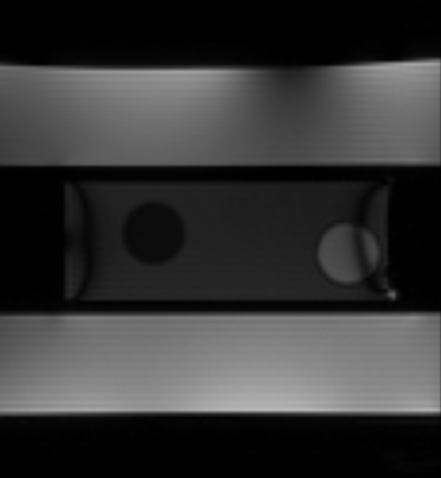
The phantom consists of two parts, both made from PMMA: an approximately torso-shaped section (length = 500 mm, height = 240 mm, width = 350 mm) that includes an off-center tubular cut-out (82 mm inner dia.) in the head-foot direction, and a smaller, movable, cylindrical phantom (diameter = 72 mm, length = 200 mm) inserted into the tubular cut-out (Fig. 1). The main body of the phantom was filled with 35 L water doped with contrast agent (17.5 ± 0.1 mM Gd-DTPA), while the cylinder was designed to be easily replaced and filled with different substances (e.g., relaxometric gels) depending upon the application.
Movement of the cylinder is controlled by a piezomotor (HR8-1-VN-3, Nanomotion Ltd., Yokneam, Israel) that is completely free of ferromagnetic parts. The motor is located approximately 1 m from the phantom, connected to the cylinder via a PEEK rod, and enclosed in a copper box designed to prevent electromagnetic interference with the MR signal. An optical incremental encoder (MR303, Micronor Inc., Camarillo, USA) was placed between the phantom and the motor to record the cylinder position. The phantom is designed in modules so that parts can be easily exchanged or refilled.
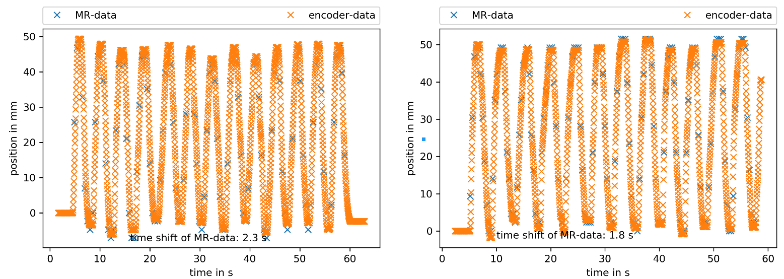
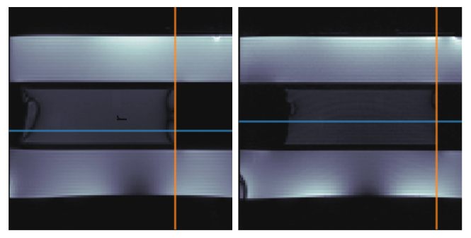
First measurements with the phantom were made in a 1.5 T MR scanner (Symphony with Tim Upgrade, Siemens, Erlangen, Germany) with the cylinder filled with a self-made relaxometric gel (0.4 ± 0.1 mM Gd-DTPA and 2.20 ± 0.02 % agarose) with relaxation times similar to those of the liver. Cylinder movement was controlled manually since the implementation of the motor and its control software was not yet finished. Software was implemented (Python 3.6) to log movement of the cylinder as measured by the encoder during MRI measurements. Two bSSFP sequences were evaluated: 1) the vendor-supplied TrueFISP (FA = 70°, TR = 3.72 ms, TE = 1.86 ms, resolution = 2 mm), and 2) a modified bSSFP sequence optimized for motion quantification [1] (FA = 70°, TR = 3.72 ms, TE = 1.86 ms, resolution = 2 mm). An edge detection tool, also implemented in Python 3.6, was used to detect movement of the cylinder in the MR images over the time.
Results
The phantom was found to be MR-compatible. No interference during the experiment was detected. Motion information extracted from the two bSSFP sequences was compared to the position recorded by the encoder (Fig. 3). The trajectory shapes of the encoder and of the edge detection tool showed high agreement, with deviations on the order of the error of the edge detection tool (one pixel = 2 mm). A time deviation between the MR- and encoder-measured position was observed. Both sets of MR images showed banding artifacts at the edge of the cylinder, but the optimized bSSFP had a low-artifact area in the middle of the cylinder, which allowed more accurate edge detection.Discussion
The high concordance of the trajectory shapes demonstrates that the phantom is an applicable device for the assessment of motion detection methods in MRI. The time deviation is assumed to result from asynchronous clocks on the logging device of the encoder and the MR scanner; adding trigger signals to the imaging sequences is expected to solve this problem. The filling of the cylinder was feasible in a user-friendly way. The cylinder could easily be changed during a measurement session, offering the user high flexibility during experiments. The modular design allows for easy extension of the current setup.Conclusion
The first step in the development of a motion phantom was successfully finished. The next step will be the programming of the motor control to be able to drive predefined trajectories. Ultimately, the developed device can be used as research tool for MR-guided therapy and as a clinical quality assessment tool to improve treatment of patients.Acknowledgements
The authors would like to thank the DKFZ precision workshop for their help in manufacturing the phantom.References
1. Friedrich, F. et al., Self-Adapting Dynamic Temporal Resolution for Optimized Reconstruction of Free-Breathing Radial Real-Time MRI, Proc. ESMRMB (2017).Figures