4144
Asymmetric-echo-based Ultrashort Echo-time (ASE-UTE) Imaging1Department of Biomedical Engineering, Sungkyunkwan University, Suwon, Republic of Korea, 2Center for Neuroscience Imaging Research, Institute for Basic Science, Suwon, Republic of Korea
Synopsis
The first 3D-UTE sequence used FID acquisition techniques using ramp sampling to minimize TE, but defining the center of k-space precisely was a difficult problem (true-k0). In case of echo acquisition containing echo peaks, it is better to define true-k0 than FID acquisition although true-k0 problem still exists because echo peaks often do not agree with true-k0 due to the echo shifts caused by system imperfections such as gradient delays and eddy currents. Here, we propose an asymmetric-echo-based 3D-UTE (ASE-UTE) sequence where echo peaks are acquired on the ramp.
Introduction
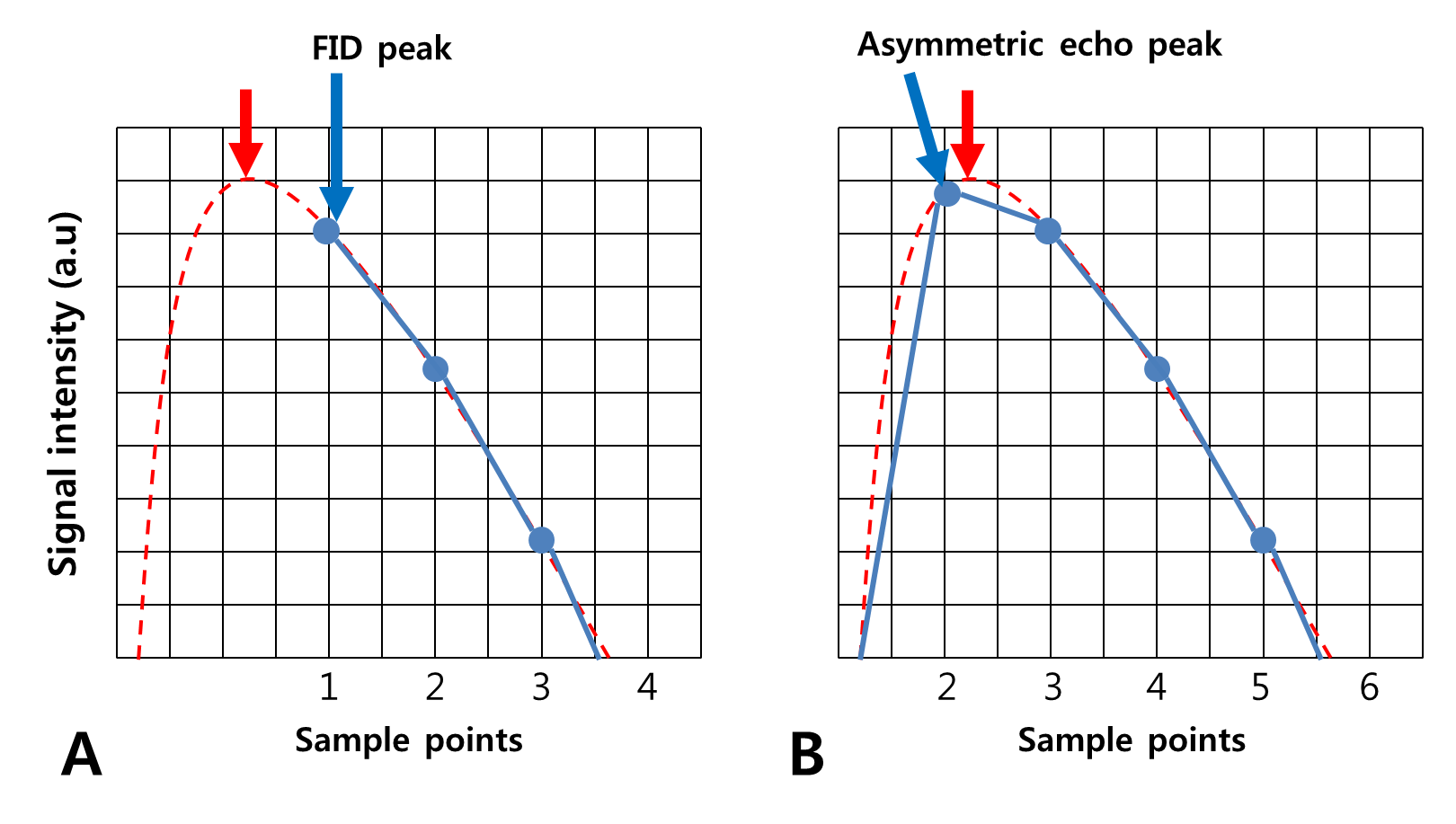
Ultrashort echo-time (UTE) imaging with radial acquisition is gaining more popularity since it can visualize very short T2/T2* species with less sensitivity to motion artifacts.1-3 Since the first 3D-UTE sequence took a FID-acquisition scheme with ramp sampling to minimize TE, it has been a challenging issue to correctly define the center of k-space (true-k0). In FID acquisition, a first couple of points are probable to be missing (Fig.1A), and incorrect registration of true-k0 may lead to some contrast-varying artifacts. In case of echo acquisition containing echo peaks, it is better to define true-k0 than FID acquisition although true-k0 problem still exists because echo peaks often do not agree with true-k0 due to the echo shifts caused by system imperfections such as gradient delays and eddy currents. While several methods have been proposed to solve the off-centering issues of k-space trajectory4-6, practically, the mean value of echo-peak positions is commonly used for defining true-k0. While this mean-peak method is approximate but working well to some extent, sometimes it also might cause a true-k0 problem when the position of true-k0 or echo peak is located within one sampling interval (Fig.1B). Here, we propose an asymmetric-echo-based 3D-UTE (ASE-UTE) sequence where echo peaks are acquired on the ramp. In terms of true-k0, it not only shares the benefit of echo acquisition, but also minimizes potential errors that can occur in the mean-value method due to a narrower k-space sampling interval on the ramp. Its performance was demonstrated in phantom imaging in comparison to original FID-based 3D-UTE at 3T.
Methods
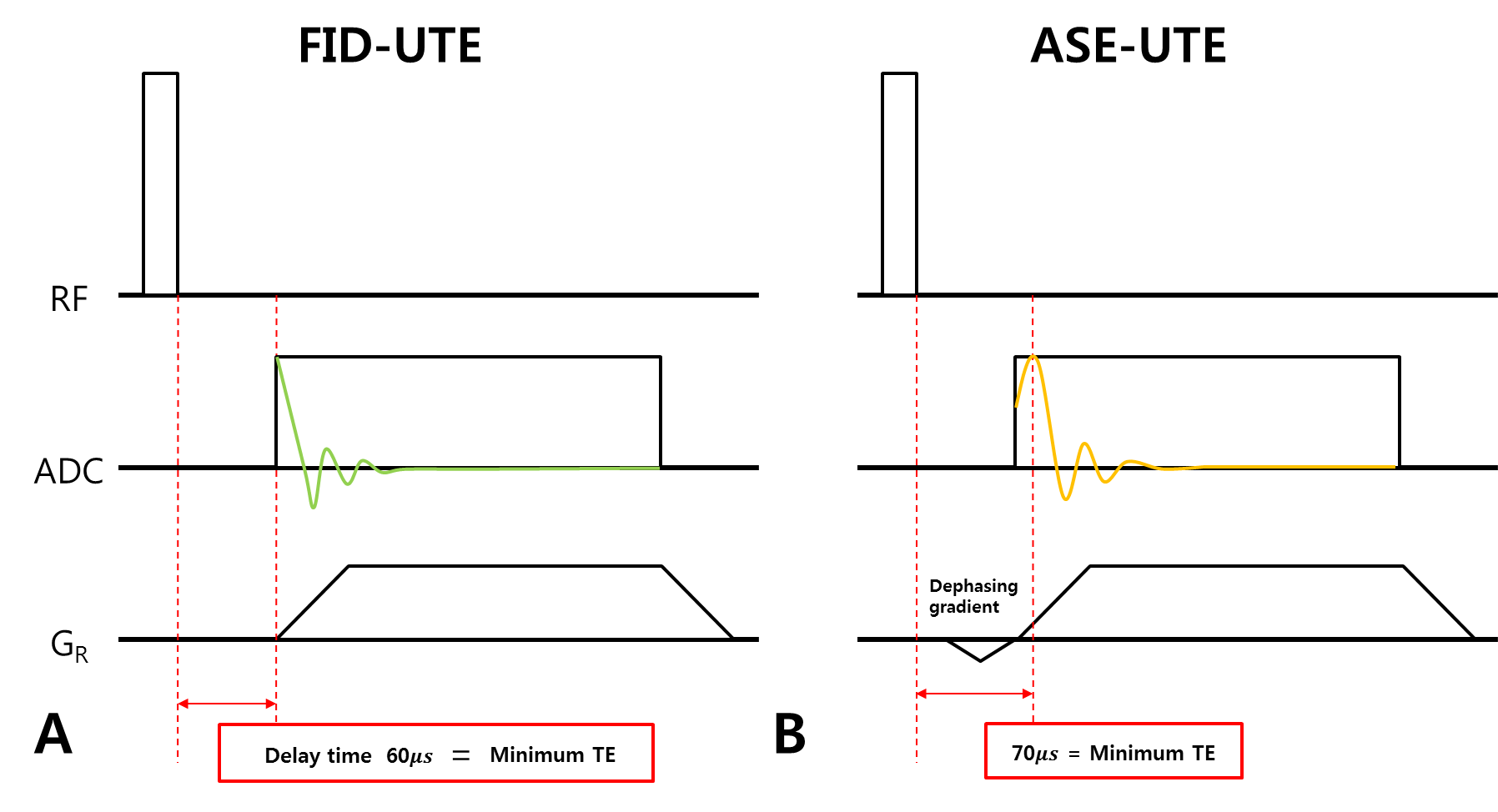
Pulse Sequence Diagram: Sequence diagrams of original FID-based 3D-UTE (FID-UTE) and ASE-UTE are shown in Figure1. While FID-UTE starts FID acquisition on the ramp (Fig.2A), ASE-UTE starts asymmetric-echo acquisition on the ramp to include the echo peak (Fig.2B). A delay time (or TE) is ~10μs longer in ASE-UTE.
Experiments: All experiments were performed on a clinical 3-T (Magnetom Trio, Siemens, Erlangen, Germany) scanner with a two-channel birdcage head coil using a ACR phantom. Common scan parameters were: TR = 3ms, FOV = 400mm3, spatial-resolution = 1.25mm3, bandwidth = 121.6kHz, flip-angle = 5°, pulse-duration = 20μs. TE was 70μs and 80μs for FID-UTE and ASE-UTE, respectively.
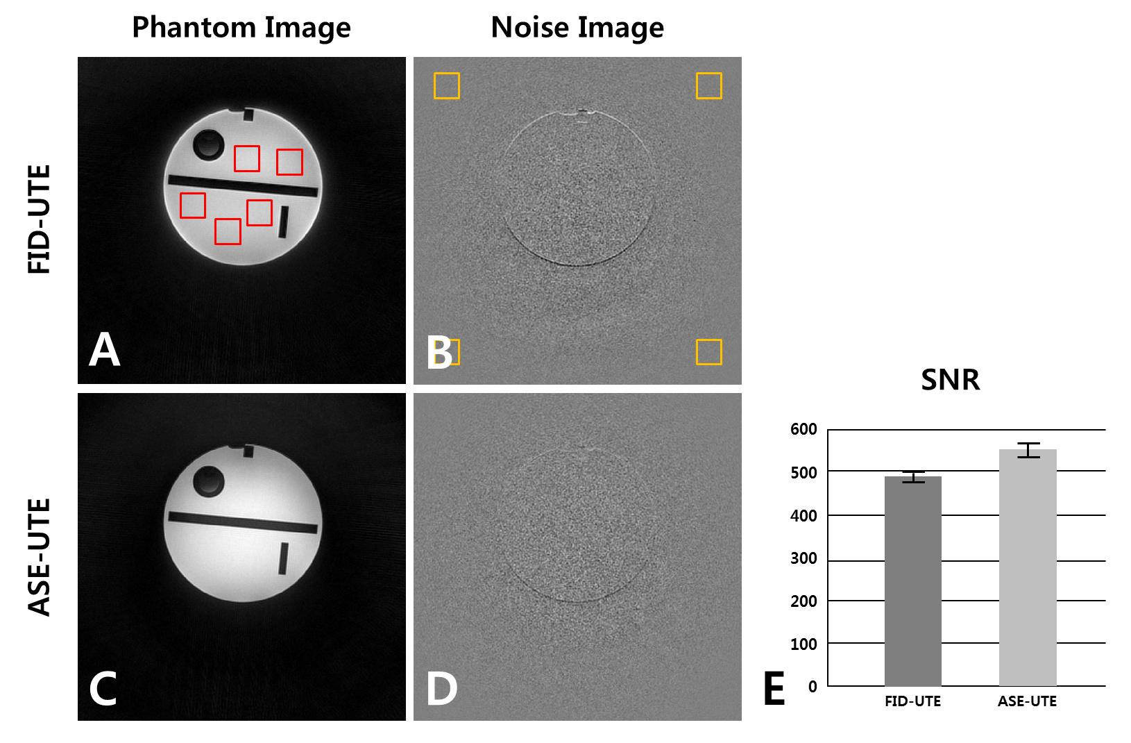
Image Reconstruction and Data Analysis:All reconstructions were performed offline with a home-built MATLAB(ver.8.2.0;R2013b) program using fast-Fourier-transform (FFT) with gridding. For ASE-UTE reconstruction, the mean value of echo-peak positions was used to define true-k0. Phantom images of FID-UTE and ASE-UTE were compared in terms of contrast-varying artifacts and signal-to-noise ratio (SNR). For SNR comparison, main signal was calculated from five different ROIs inside the phantom. Noise standard-deviation was calculated from four ROIs in the background of the subtracted image where the reconstruction-related noise pattern was effectively removed.
Results and Discussion
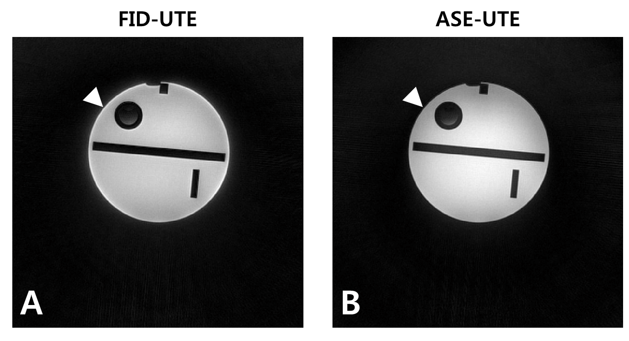
Figure3 shows representative axial slices of the ACR phantom acquired using FID-UTE (A) and ASE-UTE (B). Contrast-varying artifact is seen at the periphery of the phantom in FID-UTE (A), whereas it is much reduced in ASE-UTE due to less sensitivity to true-k0 registration (B). Figure4 shows the results of SNR comparison between FID-UTE and ASE-UTE. ROIs for main-signal calculation are represented by red square boxes and ROIs for noise calculation by yellow square boxes. SNR of FID-UTE and ASE-UTE was 491.39±17.01 and 562.15±31.16 (E), respectively, and ASE-UTE showed ~14% better SNR than FID-UTE despite a slightly longer TE(10μs). Possible explanations for better SNR of ASE-UTE are: 1) Main signals inside the phantom seem to be reduced in FID-UTE due to signal pile-up artifact. 2) In ASE-UTE, more samples are acquired around the k-space center, which might contribute to the increase of signal energy.
Conclusion
In this study, we proposed a new UTE sequence (ASE-UTE) which starts asymmetric-echo acquisition on the ramp. When compared to FID-UTE, it is less sensitive to incorrect registration of true-k0 with better SNR. We expect that the proposed sequence can be more promising in UTE imaging when it is combined with up-to-date UTE imaging techniques, e.g., limiting the FOV in one direction using a slab-selective RF pulse.7Acknowledgements
This work was supported by NRF-2017R1A2B2004944.References
1. Irarrazabal P, Nishimura DG. Fast three dimensional magnetic resonance imaging. Magn Reson Med 1995;33:656-662.
2. Bergin CJ, Pauly JM, Macovski A. Lung parenchyma: Projection reconstruction MR imaging. Radiology 1991;179:777-781.
3. Glover GH, Pauly JM. Projection Reconstruction Techniques for Reduction of Motion Effects in MRI. Magnetic Resonance in Medicine 1992;28:275–89.
4. Brodsky EK, Samsonov AA, Block WF. Characterizing and correcting gradient errors in non-cartesian imging: Are gradient errors linear-time-invariant. Magn Reson Med 2009;62(6):1466-1476.
5. Peters DC, Derbyshire JA, McVeigh ER. Centering the projection reconstruction trajectory: Reducing gradient delay errors. Magn Reson Med 2003;50(1):1-6 .
6. Block KT, Uecker M. Simple method for adaptive gradient-delay compensation in radial MRI. In Proceedings of the 19th Annual Meeting of ISMRM, Montreal, Canada, 2011. p. 2816 .
7. Johnson, Kevin M., et al. Optimized 3D ultrashort echo time pulmonary MRI. Magnetic resonance in medicine 70.5 (2013): 1241-1250.
Figures