4143
3D Golden Angle Stack-of-Stars with Anisotropic Field-of-View1Division MR Clinical Science, Philips Healthcare, Best, Netherlands, 2Dept. of Biomedical Engineering, Eindhoven University of Technology, Eindhoven, Netherlands
Synopsis
Radial sampling techniques are often used in dynamic MRI because they are robust to flow and motion, support short echo times, and have a diffuse aliasing pattern. However, standard implementations of radial imaging do not support in-plane anisotropic FOV, which leads to sampling redundancy when the object being imaged has anisotropic in-plane dimensions (e.g. abdomen, chest, spine, leg, etc.). In this work we demonstrate the feasibility of 3D golden angle stack-of-stars acquisition with an in-plane anisotropic FOV in abdominal acquisitions.
Introduction
Radial trajectories are ideal in dynamic imaging due to their favorable properties: it supports ultra-short echo times1, have robustness to flow2 and motion3, have diffuse aliasing pattern3 and are less sensitivity to undersampling. 3D golden angle stack-of-stars (3D GA-SOS) imaging allows 3D dynamic images to be reconstructed at variable temporal or spatial resolution from the same dataset4. This technique can be combined with respiratory self-gating to resolve motion artifacts without the use of any additional scan segments5. It also allows reconstruction with temporally selective data filtering techniques like KWIC6. While 3D GA-SOS allows anisotropy of the field-of-view (FOV) in the slice direction (Volume thickness), the standard implementations of 3D GA-SOS imaging do not support in-plane anisotropic FOV. This leads to sub optimal sampling and unnecessary scan time when the object being imaged has anisotropic in-plane dimensions (e.g. abdomen, chest, spine, leg, etc.). In this work, we evaluate the feasibility of in-plane anisotropic FOV for 3D GA-SOS by acquiring an optimal sampling, which matches the exact anatomy of body, in comparison with the standard 3D GA-SOS which requires a longer scan time.Methods
Larson et al.7 provided a scheme for supporting anisotropic FOV in 2D and 3D radial imaging and Wu et al.8 showed that conventional 2D golden angle sampling can be organized in an angle-normalized space and converted back to k-space such that the chosen non-uniform spoke density is preserved for arbitrary temporal window length. In conventional 3D GA-SOS, the angles have a uniform distribution because the consecutive acquired spokes are equally spaced (i.e. golden ratio Ɵ(i)=mod[2i/(1+√5),1]*π,i=0,…,N). By using the Larson method7, a fully sampled radial anisotropic FOV is computed θfull(n). Lastly, with Wu approach8 θ(i) of the ith GA spoke was computed as θ(i)=θfull [A(i)]+D(i)*∆θfull [A(i)], where A(i)=floor[indga(i)],D(i)=goldenratio(i) - A(i). In the case of 3D GA-SOS the computed radial angular distribution was repeated for every phase encoding step in the slice direction.
We illustrate this generalized mapping approach using an elliptical in-plane FOV for 3D GA-SOS. Trajectory simulations, point-spread-function (PSF) and spoke density analysis was performed. The proposed sampling scheme approach was implemented on a 1.5T Ingenia (Philips Healthcare, Best, NL). Phantom data and in-vivo axial abdominal images were acquired using a T1-TFE fat-suppressed navigator-gated 3D GA-SOS sequence in three healthy volunteers. The proposed method with elliptical FOV were compared against the isotropic FOV. Imaging parameters: FOV: 450 x 450 x 400 mm3 (fully-sampled and undersampled isotropic FOV) or 450 x 200 x 400 mm3 (anisotropic FOV), Resolution: 1 x 1 x 3 mm3, SENSE factor: 2, Half-scan factor: 0.8, Flip Angle: 10°, TR/TE: 3.3/1.34 ms, prescribed scan time was 2:03 min (fully-sampled isotropic FOV) and 1:06 min (anisotropic FOV and undersampled isotropic FOV). The sampling pattern generation and the reconstruction were performed online in the scanner. Sampling density compensation factor was calculated and taken into account during the reconstruction pipeline.
Results
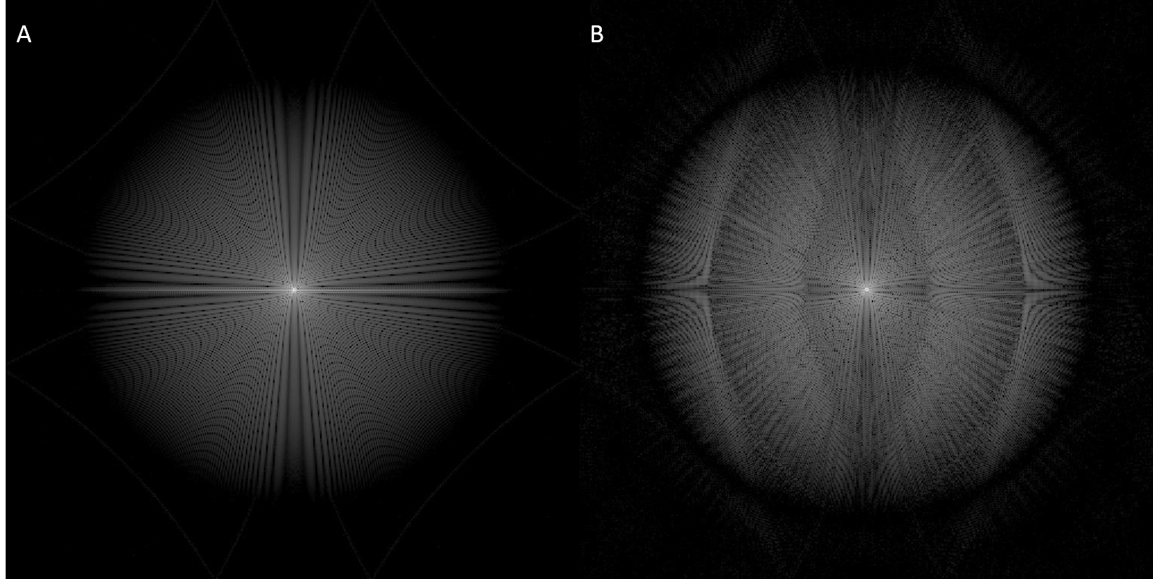
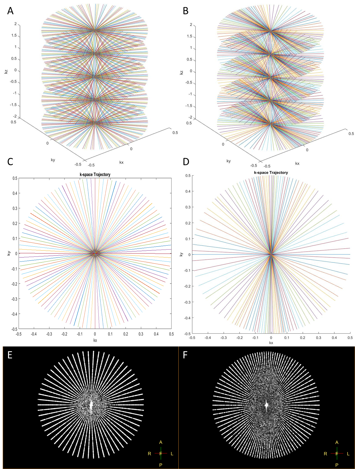
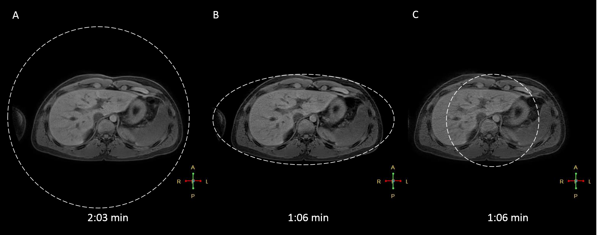
Figure 1 evaluate the PSFs and Figure 2 demonstrates the trajectories for both approaches. Figure 2A-D are based on Matlab simulations and Figure 2E-F are the exact profiles obtained with the raw data acquired on the scanner. Figure 3 compares transverse abdominal images acquiring with 3D GA-SOS with three sampling schemes: A) Fully sampled isotropic FOV; B) Anisotropic FOV; C) Undersampled isotropic FOV with the same scan time as in the B) case.Discussion
Figure 1 shows the aliasing lobes in the PSF which determines the FOV of the resulting image. Figure 2E-F demonstrate the acquired sampling density is in-line with the simulated trajectories (Figure 2A-D). Figure 3 demonstrated the feasibility of anisotropic in-plane FOV for 3D GA-SOS. Since the FOV is tailored to match the anatomy of interest this sampling scheme is more efficient when compared to the conventional isotropic FOV 3D GA-SOS technique. The image quality obtain using anisotropic FOV is comparable with the fully-sampled isotropic FOV case, which has a scan time two times longer in comparison with the anisotropic FOV approach. By undersampling the isotropic FOV case, the scan time was matched but a penalty in the image quality is observed - more streaking artifacts are present.Conclusion
Simulations and in-vivo experiments confirmed that the proposed method is able to achieve anisotropic FOV. We demonstrate the feasibility of 3D stack-of-stars imaging with in-plane anisotropic FOV, which can significantly reduce imaging times in many dynamic acquisitions where the object dimensions are anisotropic, while still maintaining image quality comparable with the isotropic FOV 3D GA-SOS.Acknowledgements
This work was supported by the European Commission within the Horizon 2020 Framework through the MSCA-ITN-ETN European Training Networks (project number 642458).References
- Robson, M. D., Gatehouse, P. D., Bydder, M., Bydder, G. M. (2003). Magnetic resonance: an introduction to ultrashort TE (UTE) imaging. J Comput Assist Tomogr., 27(6):825-46.
- Nishimura, D. G., Jackson, J. I. and Pauly, J. M. (1991), On the nature and reduction of the displacement artifact in flow images. Magn. Reson. Med., 22: 481–492. doi:10.1002/mrm.1910220255
- Glover, G. H. and Pauly, J. M. (1992), Projection Reconstruction Techniques for Reduction of Motion Effects in MRI. Magn. Reson. Med., 28: 275–289. doi:10.1002/mrm.1910280209
- Han, F., Zhou, Z., Rapacchi, S., Nguyen, K.-L., Finn, J. P., & Hu, P. (2016). Segmented Golden Ratio Radial Reordering with Variable Temporal Resolution for Dynamic Cardiac MRI. Magnetic Resonance in Medicine, 76(1), 94–103. http://doi.org/10.1002/mrm.25861
- Feng, L., Axel, L., Chandarana, H., Block, K. T., Sodickson, D. K., & Otazo, R. (2016). XD-GRASP: Golden-Angle Radial MRI with Reconstruction of Extra Motion-State Dimensions Using Compressed Sensing. Magnetic Resonance in Medicine, 75(2), 775–788. http://doi.org/10.1002/mrm.25665
- Song, H. K., Yan, L., Smith, R. X., Xue, Y., Rapacchi, S., Srinivasan, S., … Wang, D. J. (2014). Non-Contrast Enhanced 4-D Dynamic MRA with Golden Angle Radial Acquisition and K-space Weighted Image Contrast (KWIC) Reconstruction. Magnetic Resonance in Medicine : Official Journal of the Society of Magnetic Resonance in Medicine / Society of Magnetic Resonance in Medicine, 72(6), 1541–1551. http://doi.org/10.1002/mrm.25057
- Larson PEZ, Gurney PT, Nishimura DG. "Anisotropic Field-of-Views in Radial Imaging." IEEE Transactions on Medical Imaging2008; 27(1): 47-57.
- Wu, Z., Han, F., Hu, P., & Nayak, K. S. (2016). Anisotropic Field-of-View support for Golden Angle Radial Imaging. Magnetic Resonance in Medicine, 76(1), 229–236. http://doi.org/10.1002/mrm.25898
Figures