4124
Metal artifact reduction in MRI-based radiation therapy1Radiation Oncology, Washington University in St Louis, St Louis, MO, United States, 2Radiation Oncology, Barnes-Jewish Hospital, St Louis, MO, United States, 3MRI, Philips Healthcare, Cleveland, OH, United States
Synopsis
A large percentage of patients receiving MRI simulations for radiotherapy treatment planning have metal in their bodies. Often the metal is in or near the target or organs at risk. Metal creates susceptibility artifacts that can saturate the tissue signal and distort the tissue geometry. In this case report, examples of the benefits of metal artifact reduction using slice encoding for metal artifact correction (SEMAC) are presented for patients scanned at 1.5 T. Critical regions that were obscured by artifact were restored using SEMAC, thus allowing MRI-based treatment planning.
Purpose
A 2017 survey of Radiation Oncology patients receiving MRI simulations at Washington University in St. Louis indicated that 71% had metal in their bodies (not including metal introduced for radiation therapy like tandems and ovoids or fiducial markers). Thirty-seven percent of the patients had metal in the treatment field of view. The prevalence of metal in our patient population raises two major risks: 1) Patient safety; and 2) Image artifacts. In this study, we provide examples of metal artifacts and the benefits of orthopedic metal artifact reduction (OMAR) using view angle tilting (VAT) for in-plane correction and slice encoding for metal artifact correction (SEMAC) for through-plane correction of susceptibility artifacts.1,2Methods
MRI simulations were conducted using a Philips 1.5 T Ingenia MR-RT MRI system (Philips Healthcare) running software versions V5.1.7 and V5.3.1. Patients received their nominal MRI protocol. OMAR was added to the protocol when significant artifact was observed by the MRI technologist and treatment planning accuracy was at risk. OMAR is available with T1 (T1W), T2 (T2W), proton density (PDW), and Short inversion time recovery (STIR) contrast weightings. We typically used a weak setting for SEMAC (7 z-phase encodes) for cases in which the metal was nonferrous (e.g., titanium) and a medium setting (13 z-phase encodes) for cases involving ferrous metal (shrapnel, stainless steel stents, and dental braces). Alternatively, a strong setting (21 z-phase encodes) for SEMAC is available. However, the acquisition time increases with increased strength in the SEMAC setting.Results
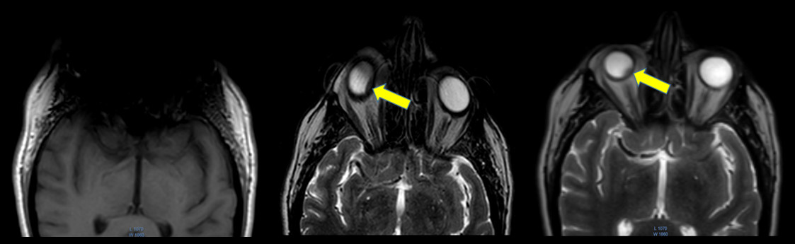
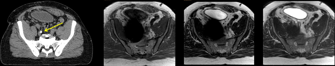
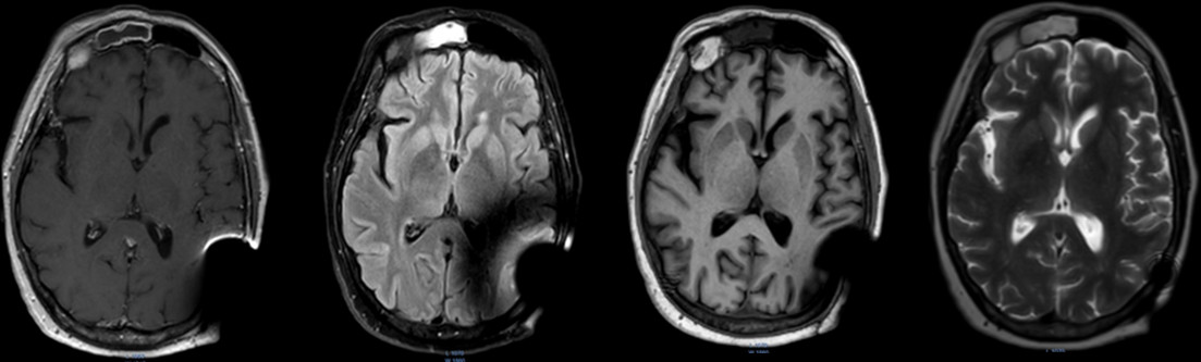
In Fig. 1, the effects of ferrous shrapnel are shown on T2W MRIs with and without OMAR in a patient being treated for prostate cancer. Although the target area can be clearly seen without OMAR, the rectum (an organ at risk) cannot be seen, thus impacting dosimetry. In Fig. 2, T2W MRI with OMAR using medium SEMAC (13 z-phase encodes) was used to rescue the MRI-based treatment planning for an eye plaque patient. Otherwise, treatment planning would have been based on CT that has poor tumor/tissue contrast, or 2D fundoscopy or ultrasonography. In Fig. 3, T2W MRI with OMAR using medium SEMAC was used to minimize artifacts from a ferrous (stainless steel) stent graft that was obscuring the target region. In Fig. 4, T2W MRI with OMAR using medium SEMAC was used in a brain tumor patient with a cochlear implant. The susceptibility artifact remained large despite the absence of the implant's magnet. Although the artifact did not affect the primary target site, it could have prevented us from identifying metastases. In Fig. 5, PDW MRI with OMAR reduced the distal bloom artifact and shaft size of the titanium tandem used in cervical cancer brachytherapy.3 The uncertainty in the location of the tandem tip can cause an error of up to 8% in the dose delivered to the tumor.4Discussion
OMAR offers significant benefits for patients with metal in the imaging field of view. Therefore, OMAR potentially improves the treatment dose accuracy. For cases in which the metal was nonferrous, weak SEMAC provided similar artifact reduction to medium SEMAC with substantially less acquisition time. The reduced acquisition time for the weak SEMAC can be used to permit signal averaging. The major disadvantage of metal artifact reduction is the increased acquisition times and reduced signal-to-noise ratio compared to 3D acquisitions that are frequently used in MRI simulations to provide high resolution images for contouring and dosimetry. Fortunately, faster metal artifact reduction methods are being developed using compressed sensing.5
Another potential application of metal artifact reduction is in the spine for patients with metal (titanium) spine implants. Our MRI simulations of the spine use 3D acquisitions with thinner (1.5 versus 3 mm thick) slices than the diagnostic MRI protocols. Therefore, 2D OMAR results in unsatisfactorily low SNR (not shown). Therefore, signal averaging and long acquisitions are required or thicker slices must be used compared to acquisitions without metal artifact reduction.
Metal artifact reduction will also be needed in the field of cardiac radiosurgery performed by MRI-Linac.6 Many of the tachycardia patients will have implantable cardiac defibrillators or pacemakers that contain ferrous components. Conventional TrueFISP sequences used in cardiac imaging and MRI-guided radiation therapy are vulnerable to magnetic inhomogeneities.
Conclusions
Metal artifact reduction has become a critical tool in MRI-based radiation therapy. It permits us to visualize tumors and organs at risk that would otherwise be obscured by artifact. The value of MRI metal artifact reduction will only increase as the prevalence of metal implants and the use of metals in radiation therapy (e.g., as fiducials and implanted radiation sources) rises.Acknowledgements
Philips Healthcare provided the research patch version (5.1.7) of SEMAC.References
1. Lu W, Pauly KB, Gold GE, Pauly JM, Hargreaves BA. SEMAC: Slice encoding for metal artifact correction in MRI. Magn Reson Med 2009;62(1):66-76.
2. Cho ZH, Kim DJ, Kim YK. Total inhomogeneity correction including chemical shifts and susceptibility by view angle tilting. Med Phys 1988;15(1):7-11.
3. Rao YJ, Zoberi JE, Kadbi M, Grigsby PW, Cammin J, Mackey SL, Garcia-Ramirez J, Goddu SM, Schwarz JK, Gach HM. Metal artifact reduction in MRI-based cervical cancer intracavitary brachytherapy. Phys Med Biol 2017;62(8):3011-3024.
4. Rao YJ, Zoberi JE, Kadbi M, Cammin J, Mackey S, Garcia-Ramirez JL, Goddu SMM, Markovina S, Schwarz JK, Grisgby PW, Gach HM. Prospective study evaluating metal artifact reduction in MRI-based cervical cancer intracavitary brachytherapy. International Journal of Radiation Oncology Biology Physics 2017;99(2 Supplement):S92.
5. Fritz J, Ahlawat S, Demehri S, Thawait GK, Raithel E, Gilson WD, Nittka M. Compressed sensing SEMAC: 8-fold accelerated high resolution metal artifact reduction MRI of cobalt-chromium knee arthroplasty implants. Invest Radiol 2016;51(10):666-676.
6. Green OL, Gach HM, Mutic S, Cuculich PS, Robinson CG. MRI-directed EP-guided noninvasive cardiac radioablation (ENCORE) for treatment of ventricular tachycardia (VT). International Journal of Radiation Oncology BiologyPhysics 2017;99(2 Supplement):S123-S124.
Figures