4090
Influence of tracking system latency on prospective motion correction1Dept. of Radiology, Medical Physics, Medical Center University of Freiburg, Faculty of Medicine, University of Freiburg, Freiburg, Germany, Freiburg, Germany
Synopsis
Tracking latency in prospective motion correction (PMC) with external tracking systems is commonly assumed to influence image quality, however no studies attempted to quantify this effect. This work presents a method to visualize latency-induced artifacts in simulated MR images. At first a MR sequence with PMC is simulated using vendor tools and recorded or synthetic motion with varying latency is added. Thereafter the effective encoding trajectory based on the exported gradient/ADC events is calculated. The resulting trajectory is used to simulate MR data with the inverse FFT, visualizing artifacts due to the tracking latency.
Introduction
In prospective motion correction (PMC) the number of external tracking devices for MRI with different specifications is steadily increasing. The most relevant are tracking accuracy, precision, update frequency, and latency. This work analyzes the influence of the latter on MR images based on real head motion data recorded in the scanner and simulated MR data.
In presence of motion, latency influences the difference of the object position compared to the position the scanner anticipates based on the available tracking data. Continuous motion in presence of gradients further results in phase shifts and k-space trajectory deformation.
The difficulty of experimental validation of the influence of latency arises from the dependency of its effects on the underlying subject motion. In an experiment the subject would be required to perform exactly the same motion multiple times with a discrepancy of less than a fraction of a voxel size and TR, which is unfeasible. Therefore we have chosen a virtual environment where all these parameters can be controlled.
Methods
The framework introduced earlier[1,2] was extended to allow for simulations of k-space data. A subjects head motion recorded at 85Hz with different added latencies (0-200ms) was fed into a virtual PMC sequence. Vendor simulation tool was used to reproduce the sequence response to the tracking data input including the gradients and ADC-phase updates identical to the real scan. These gradient waveforms, RF and ADC timings and phases were then fed into our framework together with the motion data without latency.
This framework calculated the trajectory and phase offsets within a moving object taking into account all gradients. The phase evolution in space and time was then used for a forward simulation of a virtual phantom via a non-uniform FFT on a digital phantom with a double resolution. Hereby taking into account the off-center phase offsets from the PMC-enabled sequence. Afterwards the k-space values are reconstructed with an inverse FFT. Simulations assumed an idealized hardware ignoring MR noise, tracking inaccuracy, gradient imperfections, eddy currents, etc.
A gradient echo sequence with PMC prior to the slice excitation was used in simulations[2,3] (Pixel:256x256, FOV:192x192x1.5mm, TE:35ms, TR:250ms). As this PMC-enabled sequence is known for its robustness against motion, a bipolar gradient was added with a total duration of 4ms and 8mT/m in readout and phase-encoding direction to enhance its motion sensitivity.
Results
Subject motion used for simulations was acquired in an experienced subject asked to stay still as shown in Fig.1. The presented section of approximately one hour session showing a quite substantial motion was selected under the hypothesis that this is close to a typical naive subject behavior.
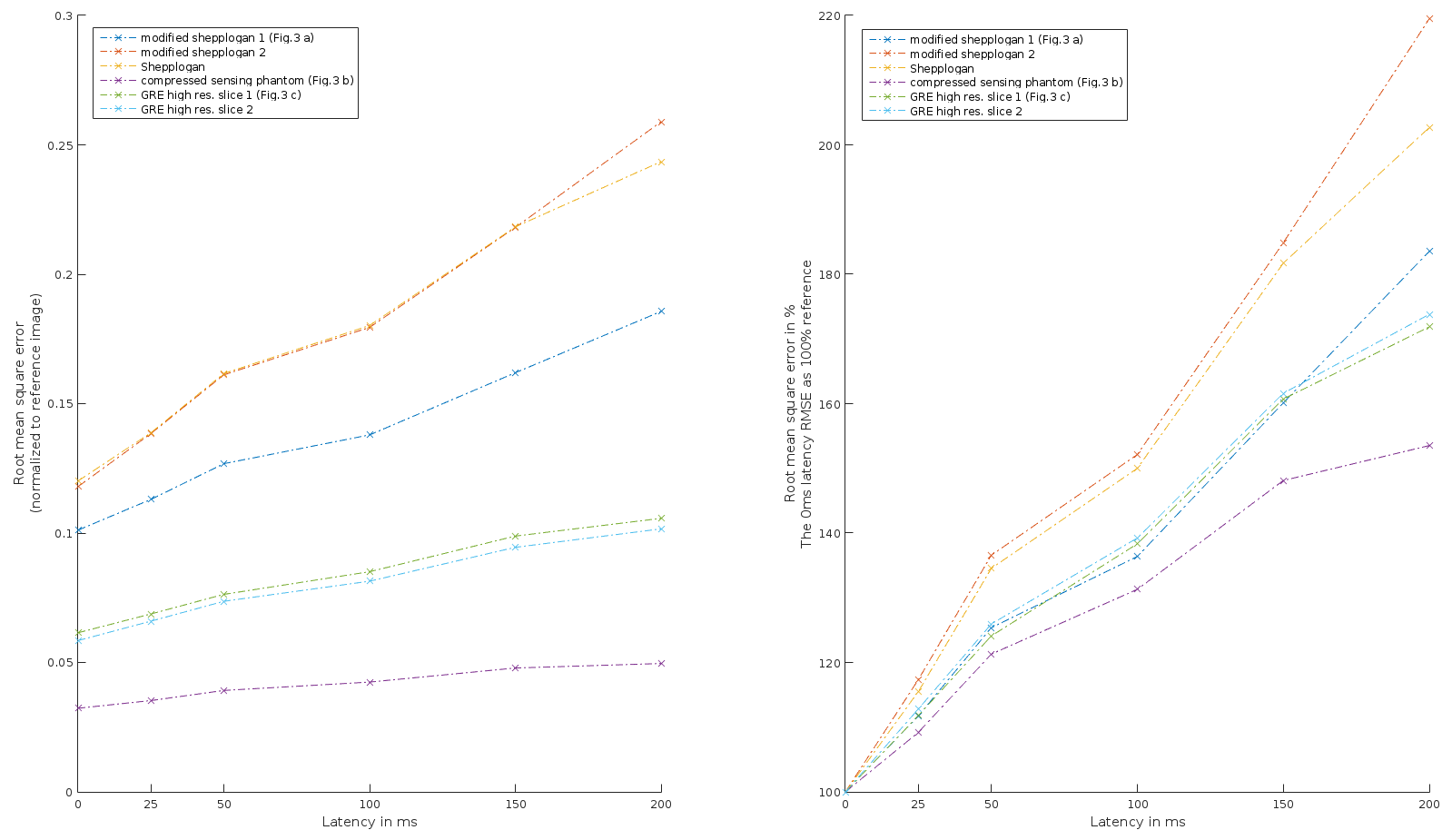
An example for the effective k-space trajectory in presence of motion with 200ms latency is shown in Fig.2. As the appearance of motion artifacts depends on the object six different virtual phantoms were used. Fig 3 shows three of them: modified Shepp-Logan phantom[4], compressed sensing phantom[5] and a HighRes GRE brain image[6]. For a reference the same phantoms were simulated without any motion. The root mean square error (RMSE) in relation to the added latencies are shown in Fig.4, normalized either to the mean image intensity or the RSME with a zero latency. A near-linear increase of the RMSE with increasing latency is visible.
Discussion
The images (Fig.3) show some artifacts for the added latency of 0ms. This is due to the fact that the motion is sampled with a rate of 11.76ms effectively adding half of that to the latency. Taking into account the period between the PMC application and the gradient echo of about 36ms (half RF pulse duration plus TE) the total latency in this case is 42ms. Furthermore, PMC does not take into account velocity-induced phase accrual which is enhanced in our case by the bipolar gradient. The visibility of the motion artifacts is further enhanced by the absence of noise.
Upon the increase of the added latency ghosting and ringing in the images becomes more pronounced. As the increase of the RMSE is approximately linear, no clear criterion for the critical added latency can be derived from the data themselves. An approach requiring the artifacts to lie under the noise floor[7] could be considered. Alternatively the added latency can be compared to the intrinsic latency on the MR side (e.g. TE). The results further motivate a combination of the PMC with a post-processing to compensate for the velocity-induced phase.
Conclusion
Latency-induced residual artifacts in PMC scale is approximately linear with the added latency. As the latency on the scanner side is typically comparable to the TE (~10-100ms) there is no great motivation for the future tracking systems to reduce the camera latency beyond that order of magnitude.Acknowledgements
This work is partially funded by NIH grant 2R01DA021146References
[1] Hucker P, Dacko M, Herbst M, et al. Fast calculation of phase accumulation due to pulsed gradients for arbitrary rigid body motion, ISMRM Proc. 2016:1941
[2] Hucker P, Zaitsev M, Framework for Effective Encoding Trajectory Calculation in Presence of Continuous Motion, ISMRM Workshop on Motion Correction in MRI & MRS 2017
[3] Zaitsev M, Dold C, Sakas G, et al. Magnetic resonance imaging of freely moving objects: prospective real-time motion correction using an external optical motion tracking system, NeuroImage, Volume 31, Issue 3, 2006, Pages 1038-1050, ISSN 1053-8119
[4] Zaitsev M, Maclaren J, Herbst M, Motion artifacts in MRI: A complex problem with many partial solutions. J. Magn. Reson. Imaging, 2015, 42: 887–901
[5] Smith D, Welch B, A non-sparse digital phantom for compressed sensing reconstruction. 2012
[6] Stucht D, Danishad KA, Schulze P, et al. Highest Resolution In Vivo Human Brain MRI Using Prospective Motion Correction. Kassubek J, ed. PLoS ONE. 2015;10(7):e0133921
[7] Maclaren J, Speck O, Stucht D, et al. Navigator accuracy requirements for prospective motion correction. Magn. Reson. Med., 2010, 63: 162–170
Figures
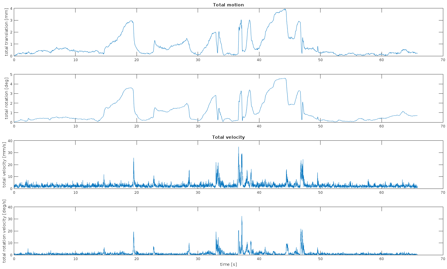
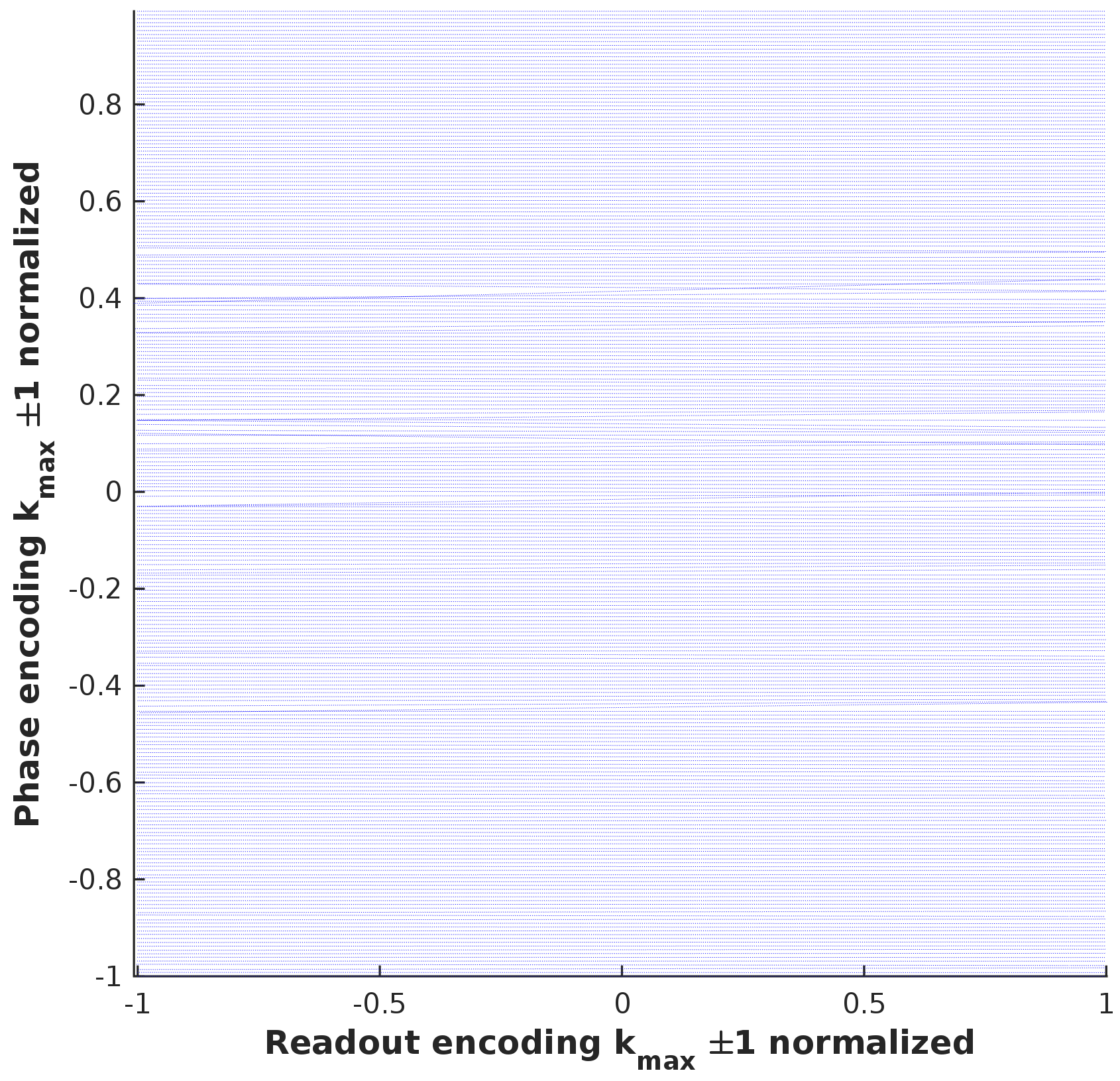
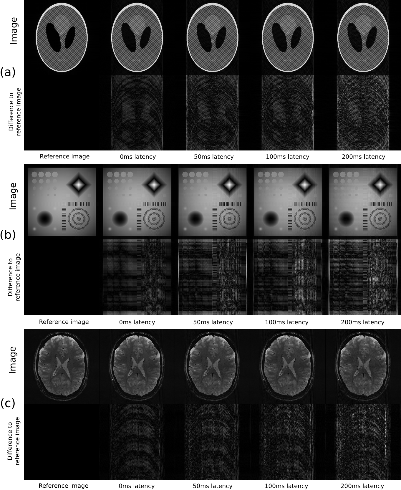
Fig. 3 Resulting simulated images with different latencies. Additionally an absolute difference image is shown based on a non-moving phantom simulation (scaling changes between rows). (a) Modified Shepp-Logan phantom. (b) Compressed sensing phantom. (c) Brain phantom based on 'Highest resolution' GRE images [6].