4074
Power to temperature conversion of AIMD under RF exposure1IT'IS Foundation, Zurich, Switzerland, 2ETH Zurich, Zurich, Switzerland
Synopsis
Determining the local tissue temperature rise caused by the RF-induced deposition of an active implantable medical device (AIMD) requires a conversion between localized power deposition to temperature (p2∆T). We investigate the quasi-static limit by which both the distributions of power and temperature are assumed to depend only on the electrode geometry (when electrically small) and independent of the current distribution along the AIMD’s wire conductor. The results confirm that p2∆T conversion can be derived without the knowledge of incident conditions to the AIMD and complete geometry of the AIMD. The relationship between p2∆T and the electrode physical geometries is summarized.
Introduction
In order to evaluate RF-induced local tissue-heating for patient with active implant medical devices (AIMD) inside MRI 1, a four-tier approach has been defined in ISO/TS 10974 2. The heating is evaluated in three steps: 1) quantify the incident RF fields that induce currents on the implants; 2) determine the worse-case RF energy deposition in the tissue next to AIMD; 3) assess the worse-case in vivo heating in the patient due to the absorbed RF energy. To obtain the maximum in vivo heating in tissue from the power deposition of 2), a conversion from RF-power deposition to ∆T is needed 3. As the distributions of the local induced power deposition and temperature within the high-heating region are dominated by the AIMD electrode geometry (provided that the electrode is electrically small), we assume that there is a static transformation from power deposition to temperature metric (p2∆T) that is independent of the incident conditions to the implant, and therefore is independent of the geometry of the wire conductor and its current distribution. The goal of the study is to 1) verify the quasi-static approximation of p2∆T conversion factor and 2) derive the empirical limit of AIMD electrode’s dimensions where the quasi-static approximation holds.Methods
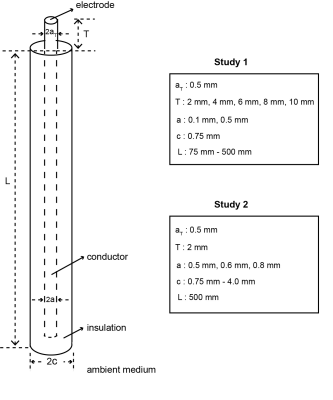
Computational electromagnetic (EM) and thermal (TH) simulations (S4L) are used to calculate the spatial distributions of power deposition and temperature changes in the vicinity of the electrode. The AIMD is embedded in an unbounded homogeneous high-permitivity medium (HPM) defined in ISO/TS 10974 (σ= 0.47 S/m, εr= 78, K= 0.62 W/m/k, Cp= 4200 J/kg/K) No thermal perfusion and thermal conduction through the AIMD conductor and insulation was assumed. The conversion factor between power deposition and the maximum local temperature rise (p2∆Tmax) is calculated from the ratio of the peak-spatial ∆T and the local deposited power in the vicinity of the electrode. The power deposition is calculated by integrating the volume enclosing the –30 dB contour of the distribution obtained from the EM simulations and peak-spatial ∆T is obtained from the TH simulations at 1200 s. The p2∆Tmax conversion factors for AIMD samples of different electrode geometries and lead physical geometries are derived. Figure 1 shows the AIMD parameters considered in this work. We divided this work into two parts, as described below:
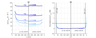
Study 1: The p2∆Tmax is derived for different electrode geometry, T = 2 – 10 mm. Two families of AIMD: (a, c) = (0.1 mm, 0.75 mm) and (0.5 mm, 0.75 mm) are considered. The quasi-static limit is investigated by varying the conductor length of each AIMD family from L = 75 – 500 mm.
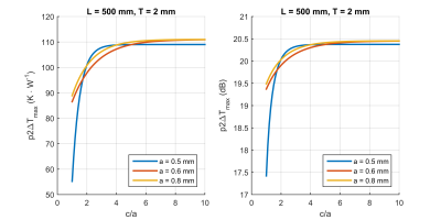
Study 2: The p2∆Tmax is derived for smallest electrode geometry, T = 2 mm. The dependent of p2∆Tmax on both conductor and insulation geometries are investigated from 15 families of AIMD with (a, c) = (0.5 mm, [0.75, 1.0, 1.5, 2.0, 2.5] mm); (0.6 mm, [0.9, 1.2, 1.8, 2.4, 3.0] mm); (0.8 mm, [1.2, 1.6, 2.4, 3.2, 4.0] mm) are considered. The conductor length of each AIMD family is fixed to L = 500 mm.
Results
Study 1 demonstrates that for small electrodes, p2∆Tmax are independent of the AIMD wire length. Figure 2 illustrates the asymptotic behavior of p2∆Tmax towards L = 500 mm for both (a, c) = (0.1 mm, 0.75 mm) and (0.5 mm, 0.75 mm) families. An empirical limit of L/T >= 25 is derived from the results to define the quasi-static regime of p2∆Tmax. When this L/T limit is satisfied, p2∆Tmax can be derived within 0.5 dB of the asymptotic values. In Study 2, T = 2 mm and L = 500 mm were selected and we investigate the effect of p2∆Tmax due to the changes in both a and c. 15 combinations of (a, c) were considered. The results show a dependency of p2∆Tmax on the insulation-conductor thickness ratio (c/a) and p2∆Tmax of all AIMD samples approach a single limit when c/a approaches a large value (c/a > 2).Conclusion
Generic AIMDs of different geometrical properties are used in this work to validate the quasi-static assumption of p2∆T conversion factor. p2∆T were derived for five electrode geometries: 2,4,6,8,10 mm-long. We demonstrated that for a given electrode geometry, a first approximation of p2∆T conversion factor can be evaluated by assuming a simple wired conductor with L/T > 25 and c/a > 2. We anticipate that p2∆T for in vivo estimation can be derived similarly, with the incorporation of appropriate thermal properties and boundary conditions of the local tissue distribution.Acknowledgements
No acknowledgement found.References
1. Maurits K.K, Lambertus W.B, Henk F..M.S, Chris J.G.B. Heating around intravascular guidewires by resonating RF waves. JMRI, 2000;12:79–85.
2. ISO/TS 10974, Assessment of the safety of magnetic resonance imaging for patients with an active implantable medical device, (Draft), 2016.
3.Yeungr C.J, Susil R.C, Atalar E. RF Safety of Wires in Interventional MRI Using a Safety Index. MRM, 2002;47:187-193.
Figures


