4067
Generation of a “virtual population” of deep brain stimulation patient models for MRI safety studiesBastien Guerin1,2, Mathias Davids1,3, Darin Dougherty2,4, Leonardo Angelone5, and Lawrence L. Wald1,2
1Radiology, Massachusetts General Hospital, Charlestown, MA, United States, 2Harvard Medical School, Boston, MA, United States, 3Computer Assisted Clinical Medicine, Heidelberg University, Heidelberg, Germany, 4Psychiatry, Massachusetts General Hospital, Charlestown, MA, United States, 5DBP/OSEL/CDRH, US Food and Drug Administration, Silver Spring, MD, United States
Synopsis
We develop and disseminate a “virtual population” of five deep brain stimulation (DBS) patient models. The models are high-quality, watertight, topologically correct, non-intersecting surface meshes that can be used in conjunction with Finite Element Method (FEM) tools such as Ansys HFSS and CST. They are realistic descriptions of actual DBS patients anatomy (internal air, bone and “average tissue”) as well as the entire DBS path including the Implantable Pulse Generator (IPG) and extension cables. We hope the models can be useful for assessment of inter-subject variability of RF-safety metrics such as SAR and temperature.
Introduction
Deep brain stimulation (DBS) is a therapeutic strategy approved for the treatment of movement disorders [1]. Despite the success of DBS, the mechanisms of action of DBS are not well understood, which is slowing its translation to psychiatric disorders [2]. High-field (3T) fMRI is the ideal modality to characterize brain functional network modulations due to DBS, but is currently contra-indicated due to the risk of RF-induced heating. We propose a “virtual population” of five realistic DBS patient models for simulation of this effect. Our models are high-quality, watertight, topologically correct, non-intersecting surface meshes that can be used in conjunction with Finite Element Method (FEM) tools such as Ansys HFSS and CST.Methods
Patients & IRB: Under an approved protocol, we searched the Research Patient Data Registry system of our institution for DBS patients who received head, neck or abdomen CT examinations for reasons either related or unrelated to their DBS condition. 107 patients were found, including 7 hospital employees who were excluded. 10 patients were selected who had received both a head and neck CT scan after the DBS implantation. Five patients were further selected because of the superior quality of their CT images (4 males, 1 female. Age 52 ± 27.7 y.o, with minimum of 19 and maximum of 79 y.o). Virtual CT: Only one of the 5 patients received a CT examination covering the entire length of the DBS implant (i.e., from IPG to top of the head). For all other patients, extraction of the entire DBS implant model required stitching the head and neck CTs. This was performed by manual registration using Freeview. The stitched CT image was down-sampled from 0.625 mm isotropic to 1 mm isotropic. Creation of the DBS implant model: Creation of the DBS model from the virtual CT volume was performed as described in [3]. The steps involved are summarized in Figs. 1&2. As shown in Fig. 3, the central process is a previously-published optimization procedure that automatically deforms the CT-derived DBS path in order to guarantee that 1) the curvature is smaller than 1/R at every point along the path and 2) that the distance between any two segments of the path is greater than R, thus removing cable intersections (R is the DBS cable radius). We modeled a generic DBS lead model, with four 1 mm-long, 1.27 mm-diameter electrodes, based on lead model 3389 (Medtronic Inc., Minneapolis, MN) . For simplification, we did not model the helicoidal structure of the internal conductor wires but four straight cables running parallel to the main path. Creation of the body surface mesh: Robust generation of body mesh models was performed following the steps outlined in Fig. 4. Manual cleanup of the segmented volume (Fig. 4, STEP #3) was by far the most time consuming step, requiring an entire day of work per patient. All steps were performed in Matlab using custom code, except for STEP #5 which was performed using MeshMixer [4]. The final step was performed using the methodology detailed in abstract #3964 [5]. Dissemination: Our goal is to disseminate these models as widely as possible. Our IRB currently prevents us from posting the models online however -- to obtain them, please contact Bastien Guerin guerin@nmr.mgh.harvard.edu.Results
Fig. 5 shows four of the five body models (the
last one is still in preparation). Left/right reconstructed DBS paths length
(in mm) were 610/602 (patient A), 595/590 (patient B), 719/625 (patient C) and
862/879 (patient D). In theory, depending on the exact extension cable used by
the neurosurgeon, total cable lengths should be either 600 mm or 800 mm. Deviations
from these reference values are due to path simplifications, for example at the
extension cable-IPG connection point. All models were successfully loaded and
analyzed within Ansys HFSS, showing no topology problems or simulation errors.Conclusion
We have initiated the assembly of a “virtual population” of DBS patient models to assist with MRI safety evaluation in this patient cohort. Although we strived to produce highly realistic models, these are necessary simplifications of actual patients. Nevertheless, the models represent the “next step” in DBS modeling as they allow the assessment of inter-subject variability of RF-induced heating, which is often missing in the literature [6-12].Acknowledgements
NIH grants K99/R00 EB019482. The mention of commercial products, their sources, or their use in connection with material reported herein is not to be construed as either an actual or implied endorsement of such products by the Department of Health and Human Services.References
[1] Mayberg, H. S., et al. (2005). "Deep brain stimulation for treatment-resistant depression." Neuron 45(5): 651-660. [2] Riva-Posse, P., et al. (2017). "A connectomic approach for subcallosal cingulate deep brain stimulation surgery: prospective targeting in treatment-resistant depression." Molecular psychiatry. [3] Guerin B et al (2017). “Patient specific modeling of deep brain stimulation patients for MRI safety studies”. Proceedings of the ISMRM, pp 12. [4] http://www.meshmixer.com/ [5] Davids M et al (2018). “Automatic Generation of Topologically Correct, High Quality, Simulation-Ready Finite-Element Tetrahedral Body Models from Voxel and Surface Data”. Proceedings of the ISMRM. [6] Iacono M et al. (2013). "MRI-based multiscale model for electromagnetic analysis in the human head with implanted DBS." Computational and Mathematical Methods in Medicine; DOI: 10.1155/2013/694171 [7] Cabot E et al. (2013). “Evaluation of the RF heating of a generic deep brain stimulator exposed in 1.5 T magnetic resonance scanners.” Bioelectromagnetics 34(2): 104-113 [8] Eryaman Y et al. (2014). “Parallel transmit pulse design for patients with deep brain stimulation implants”. Magnetic Resonance in Medicine 73(5): 1896-1903 [9] Golestanirad L (2016). “Local SAR near deep brain stimulation (DBS) electrodes at 64 and 127 MHz: A simulation study of the effect of extracranial loops”. Magnetic Resonance in Medicine; DOI: 10.1002/mrm.26535 [10] Kozlov M (2017). “Applicability of Lead Electromagnetic Model for an External Wire with Skin Contact”. Proceedings of the ISMRM, pp 2623. [11] Angelone LM, Ahveninen J., Belliveau JW, Bonmassar G. Analysis of specific absorption rate (SAR) at 3T MRI with variable Deep Brain Stimulation (DBS) lead resistivity. IEEE Trans Medical Imaging, 2010;29(4):1029-1038. [12] Serano P, Angelone LM, Katnani H, Eskandar E, and Bonmassar G*. A Novel Brain Stimulation Technology Provides Compatibility with MRI. Scientific Reports. 2015;5:9805.Figures
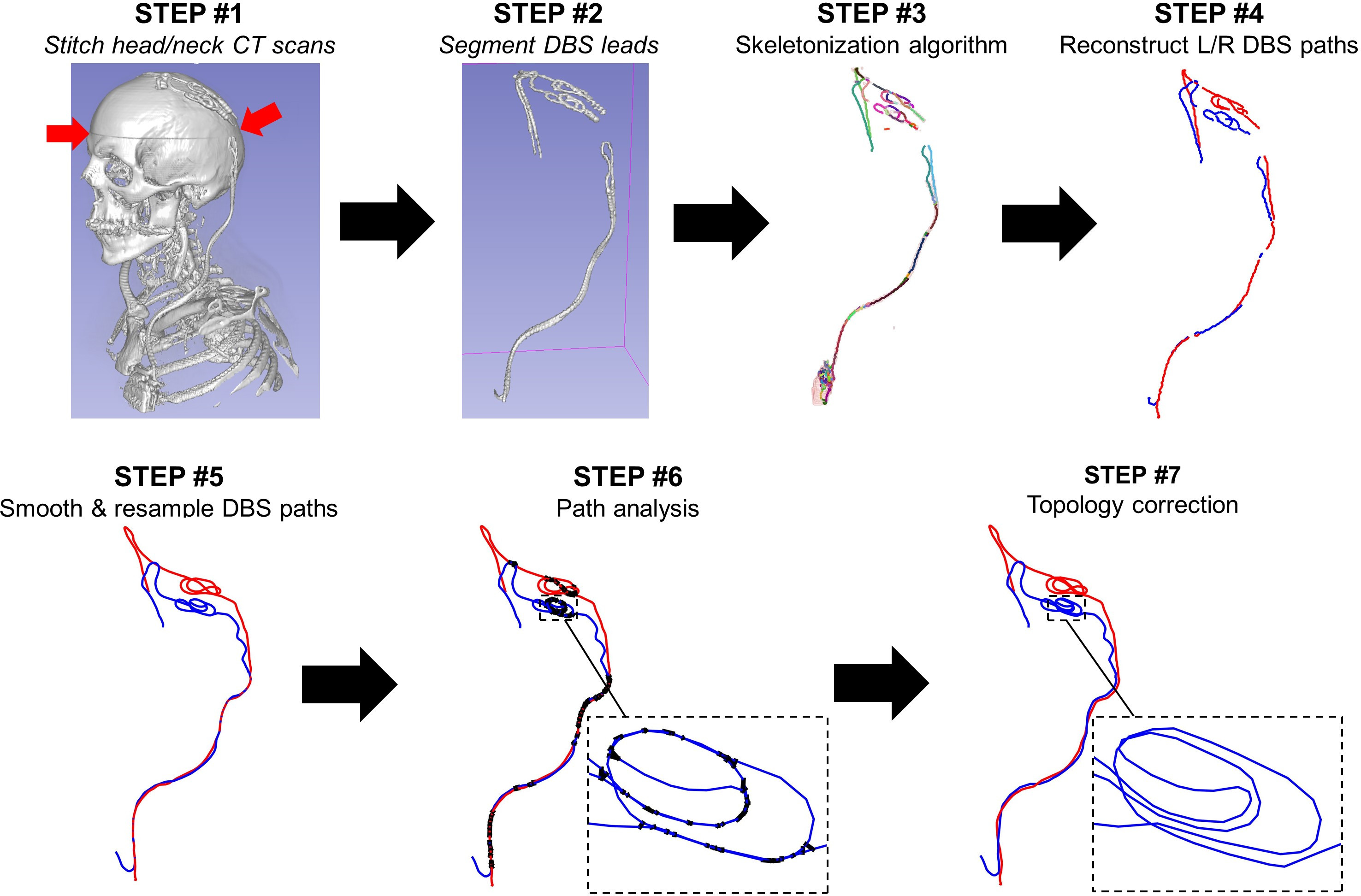
STEP #1: The head and neck CTs are
stitched into a “virtual CT” covering the entire length of the implant. STEP
#2: Segmentation of the DBS voxels by thresholding. STEP #3: Skeletonization
and reconstruction of the DBS path branches. STEP #4: Manual
reconstruction of the DBS path from the skeleton branches. STEP #5: Smoothing
and resampling. STEP #6: Topological analysis of the path. Black thick
lines between segments correspond to segment pairs that are closer than the cable
diameter R – thus indicating a cable intersection. STEP #7: Automatic
optimization procedure for correction of cable intersections and curvature
violations.
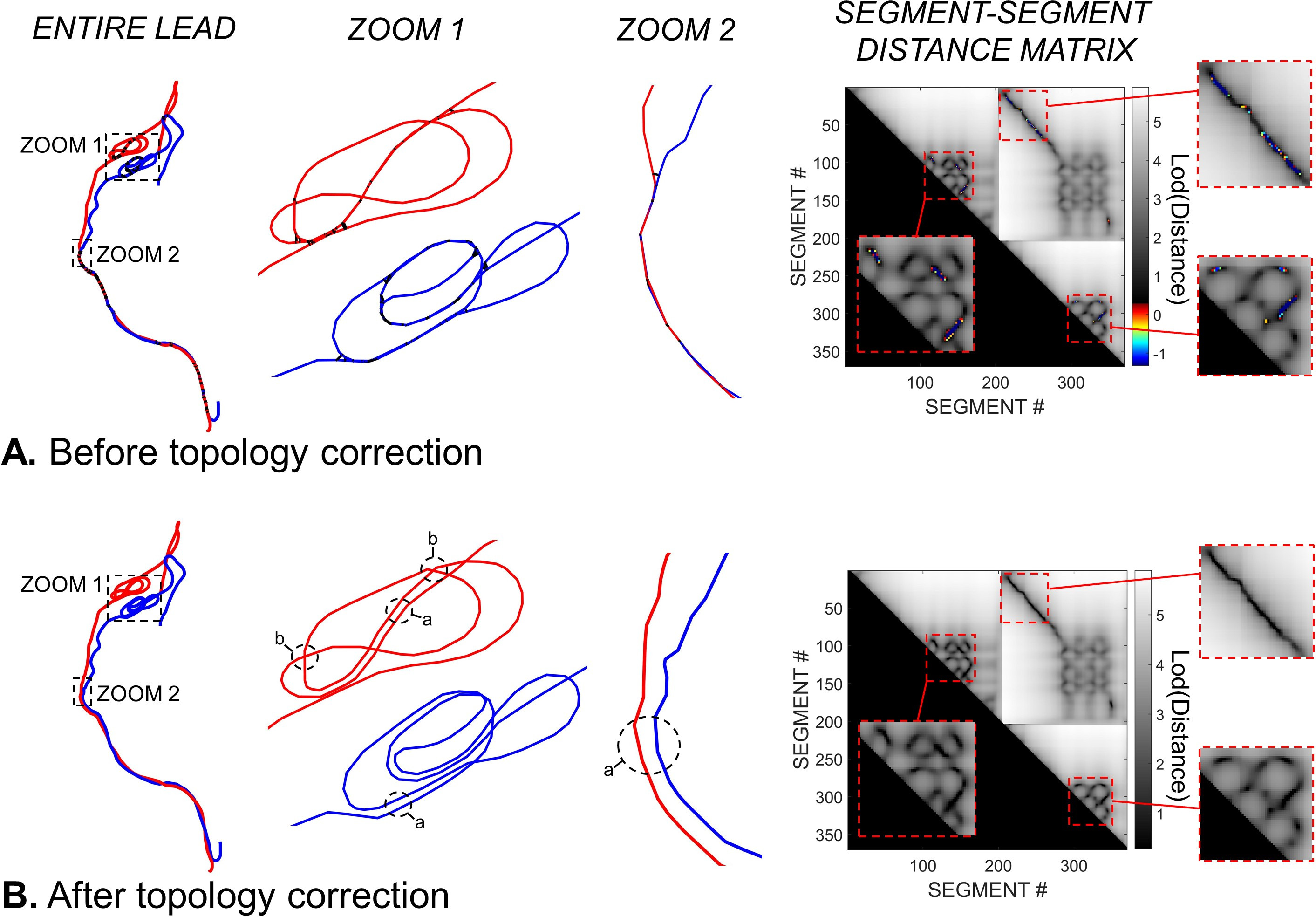
A. DBS path before topology correction. The
zooms show path regions with many intersections (thick black lines). The last
column shows the distance-distance (in mm) matrix between all segment pairs (the
left and right leads were concatenated to capture all possible intersections). The
grey scale corresponds to distances greater than R (non-intersecting segments).
The color scale corresponds to segment pairs that are closer than R (intersecting
segments). B: DBS path after topology correction. All intersections have
been removed. Balloons “a” and “b” show two kinds of topology corrections: Parallel
tracks (“a”) and bridges (“b”).
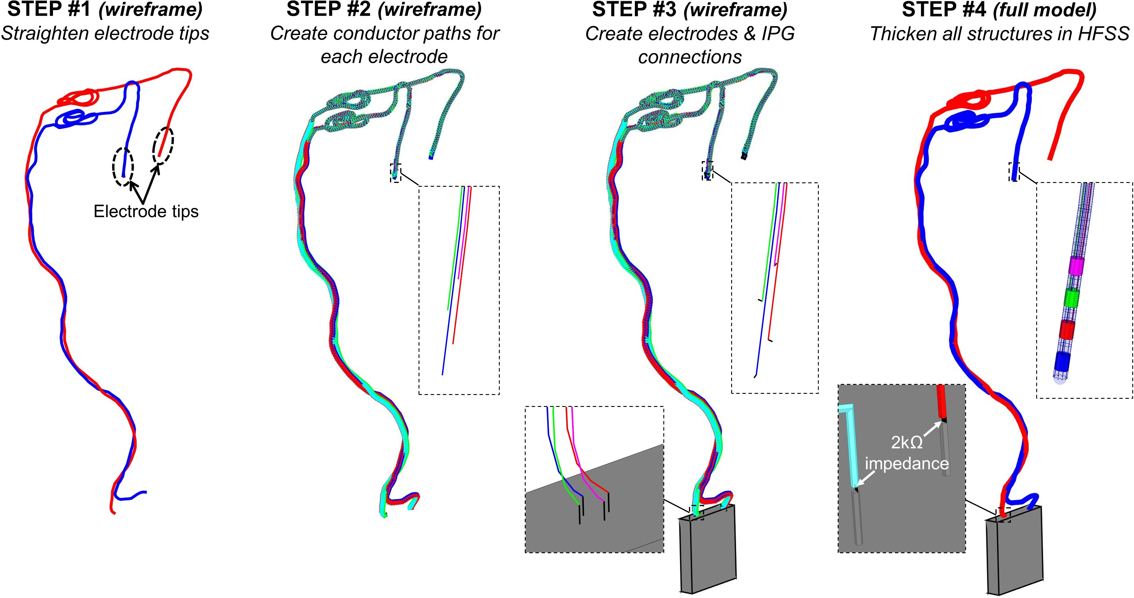
Creation of the DBS implant model from the DBS
path. STEP #1: Straightening of the path at the electrode tips. STEP
#2: Four cable conductors are created that run parallel to the main path. STEP
#3: The IPG (gray box) is added to the model as well as small line segments
connecting the four conductor paths to the electrodes and the IPG. STEP #4:
Line segments are imported in HFSS and are thickened to create the electrodes,
conductor paths and insulation sleeves. The 2000 Ω resistors model the
input impedance of the IPG at RF frequencies.
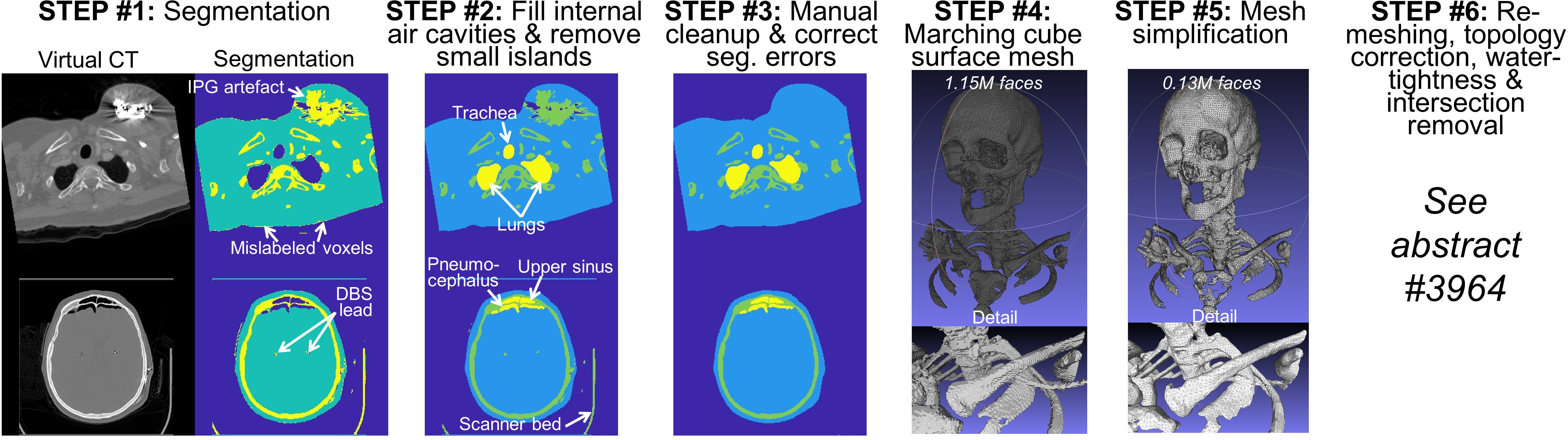
Processing pipeline for creation of the body
model (surface mesh).
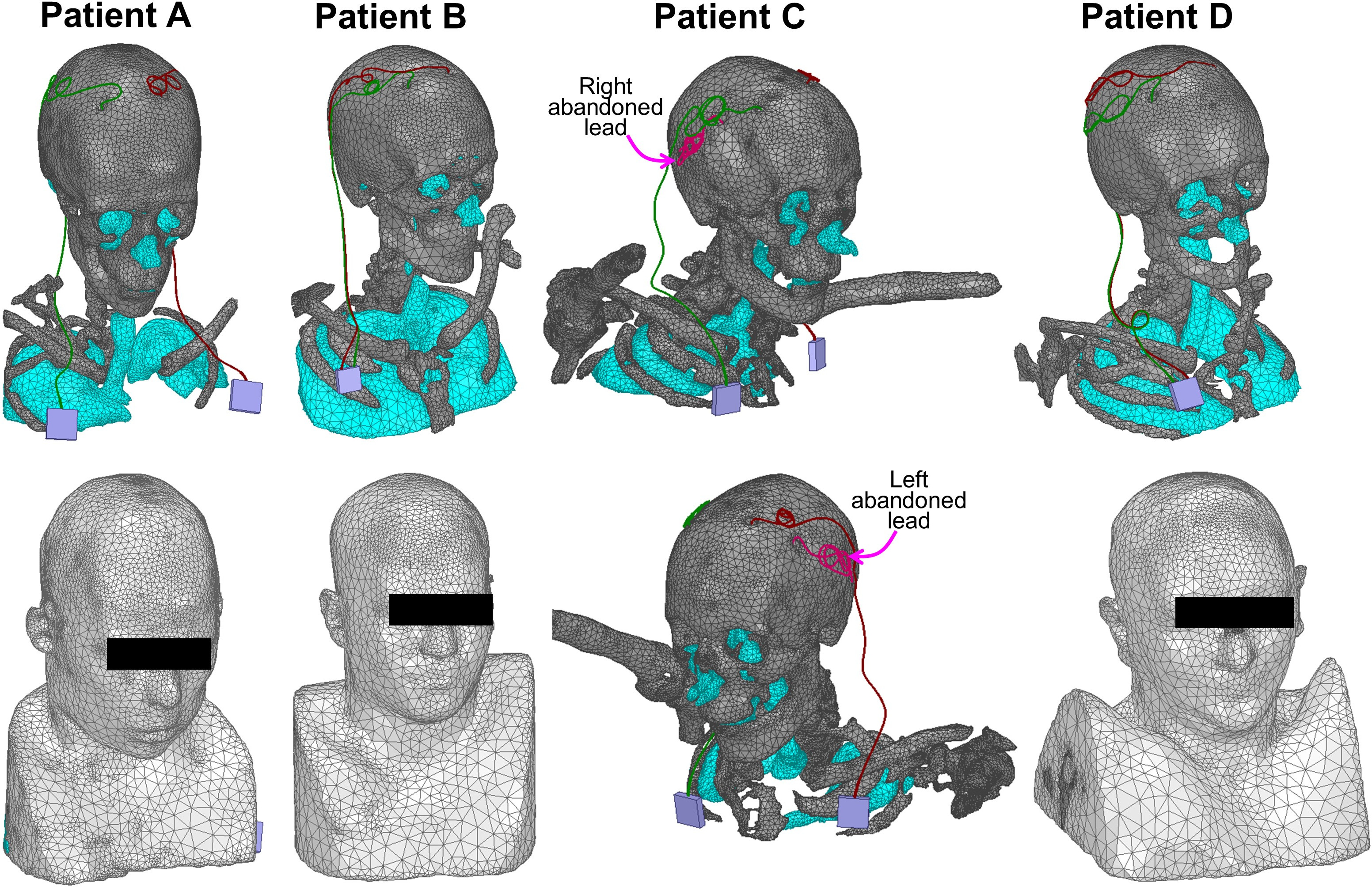
Visualization of four of the five surface patient
models. All models were imported in HFSS and were successfully validated using
the “model analysis” tool. Patient C is a bit unusual: The model has two leads
connected to bilateral IPGs as well as two abandoned leads on the left and
right sides. The reason why these leads were abandoned is not clear. The impact
of this unusual DBS configuration on MRI safety is also not well understood and
require further investigation.