4066
Reducing heating of implanted leads through High-Dielectric Capacitive Bleeding of Current (HD-CBLOC): concepts, simulations and experimental results1Building 75, Massachusetts General Hospital, Charlestown, MA, United States, 2Radiology, Massachusetts General Hospital, Charlestown, MA, United States, 3Department of Life Science Engineering, Institute of Medical Physics and Radiation Protection, Giessen, Germany
Synopsis
RF heating of conductive implants such as those in cardiac pacemakers and deep brain stimulation devices remains a major issue limiting access to MRI for hundreds of thousands of patients. Here we present a novel technique we call High-Dielectric Capacitive Bleeding of Current (HD-CBLOC) to develop an implanted lead with significantly reduced RF heating. The lead uses a high-permittivity insulating coating around the conductive wires to enable a distributed capacitive dissipation of RF currents along the length of the lead and thus reducing the energy deposition at the tip. Experiments show the configuration reduces heating by more than 15-fold during scans at 1.5 T. Simulations predict a similar effect at 3T and 7T.
Introduction
RF heating of conductive implants such as those in cardiac pacemakers and deep brain stimulation devices remains a major issue limiting access to MRI for hundreds of thousands of patients [1]. Here we present a novel technique we call High-Dielectric Capacitive Bleeding of Current (HD-CBLOC) to develop an implanted lead with significantly reduced RF heating. The lead uses a high-permittivity insulating coating around the conductive wires to enable a distributed capacitive dissipation of RF currents along the length of the lead and thus reducing the energy deposition at the tip (Figure 1). Experiments show the configuration reduces heating by more than 15-fold (from >30°C to <2°C) during scans at 1.5 T. Simulations predict a similar effect at 3T and 7T.Methods
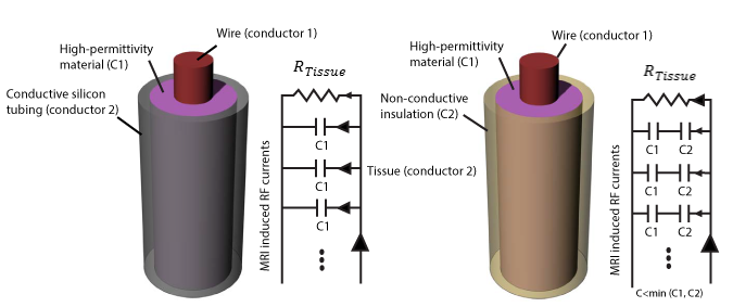
Concept: Figure 1 shows a schematic describing the formation of a distributed high-capacitive element between the wire and the tissue when a high-dielectric constant (HDC) material is used. The HDC material should be either in direct contact with the conductive tissue (if the material is solid) or in contact with a conductive tubing (as in our case where the dielectric material is in the form of a paste which needs to be contained.) The net effect is to form a distributive capacitance between the lead and conductive tissue. The resulting circuit will dissipate RF energy through the length of the lead (through the distributed capacitance) rather than forcing all current to exit at the tip.
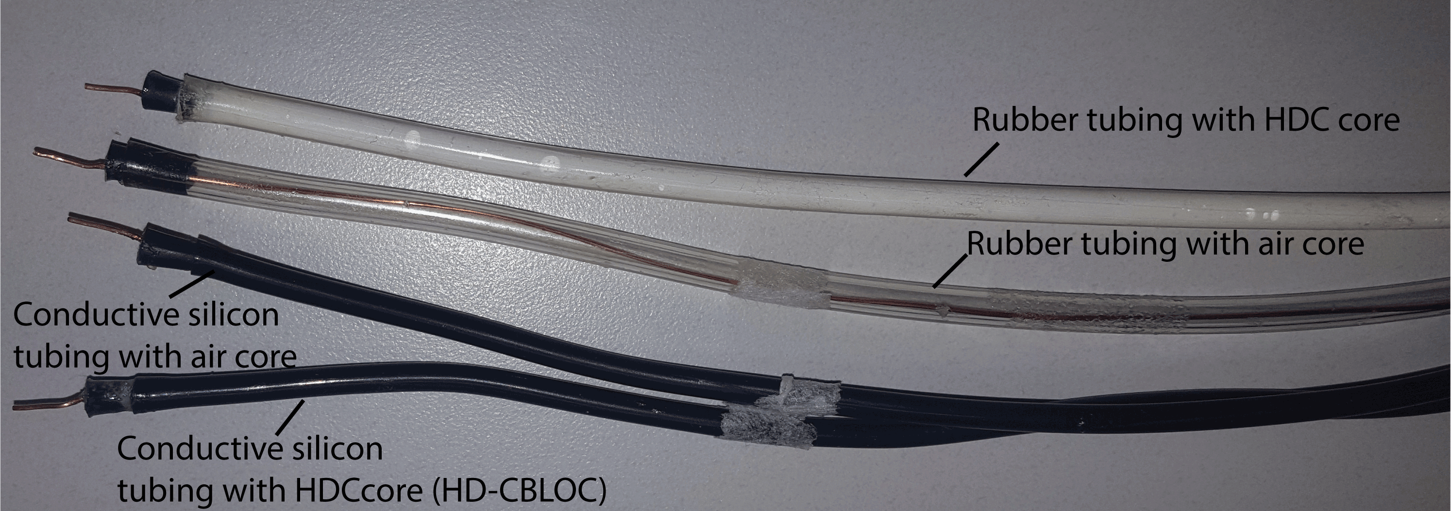
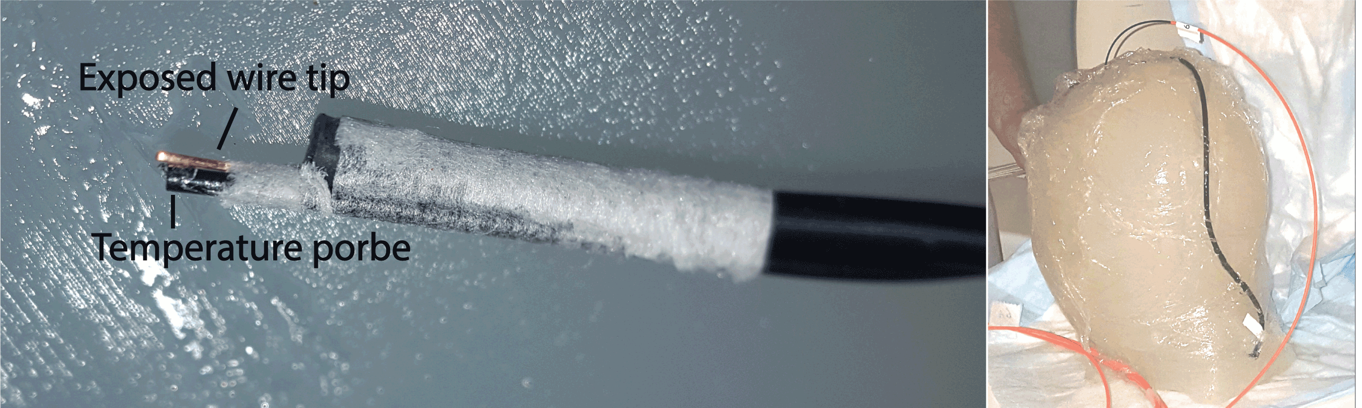
Experiments: A high-permittivity paste () was prepared by mixing Barium titanate (BaTiO3) powder (Sigma Aldrich, St Louis MO) with distilled, de-ionized [2]. Insulated copper wires of 49 cm length were used to prepare the implants. Wires were unvarnished at the tip to expose 1 cm of bare copper, and passed through a rubber stopper and into (a) an empty rubber tubing, (b) the rubber tubing filled with the HDC paste, (c) an empty conductive silicon tubing and (d) the conductive silicon tubing filled with the HDC paste (HD-CBLOC) (Figure 2). Leads were implanted in agar head phantoms and temperature at their tip was measured using MR compatible fiber optic sensors (Figure 3). MR exams were performed at a 1.5 T Scanner (Siemens Healthineers, Magnetom Avanto, TIM system, Erlangen, Germany) using a T1 weighted pulse sequence with TR= 400 ms, reported SAR of100% and, total scan time of 3 minutes.
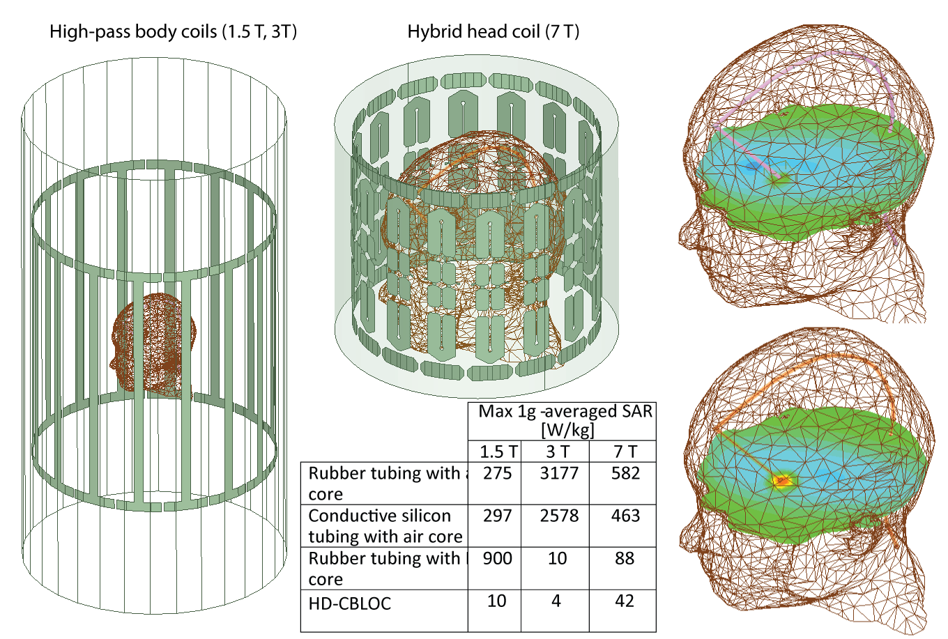
Simulations: Electromagnetic simulations were implemented in ANSYS Electronics Desktop (HFSS 16.2, Designer, ANSYS Inc. Canonsburg, PA) [3]. Models of two high-pass birdcage body coils at 64 MHz (1.5 T) and 127 MHz (3 T), and a hybrid head only coil at 297 MHz (7 T) were implemented. The maximum 1g-averaged SAR was calculated in a 20mm×20mm×20mm cubic volume around the tip of the wire (Figure 5).
Results
SAR Calculations: Our simulations with 1.5 T body coil predicted a 27-fold SAR reduction when a HD-CBLOC lead was implanted in the head phantom compared to the lead with an empty rubber tubing. HDC filling only reduced the SAR when the tubing was conductive, or when the HDC was in direct contact with the tissue. In the case of a rubber tube filled with HDC paste, the SAR at the tip of the wire was increased by almost 3-fold with respect to the empty rubber tubing, confirming our hypothesis that direct contact with a conductive medium (either tissue or the conductive tubing) is required to allow the capacitive dissipation of currents.
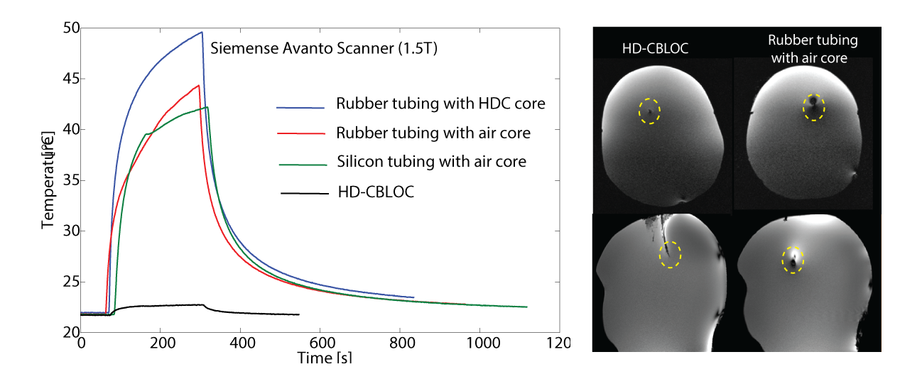
Temperature measurements: As predicted by simulations, the maximum heating was observed for the rubber tubing filled with the HDC (, whereas the HD-CBLOC lead demonstrated a significantly reduced heating at the tip . The empty rubber tubing and empty silicon tubing showed similar heating slightly less than the HDC-filled rubber tubing (). Interestingly, the metal artifact was also significantly reduced when HD-CBLOC implants, rendering the tip of the wire directly observable in both axial and sagittal images. Simulations at higher fields: Simulations with body coil at 3 T predicted a 1000-fold SAR reduction at the tip of the wire with conductive silicon tubing filled with HDC material compared to wire with empty rubber tubing. In contrast to 1.5 T, at 3 T the rubber tubing filled with the HDC exhibited reduced SAR compared to empty tubing. Similar pattern was observed at 7 T. We are now in the process of completing experiments at these higher fields to confirm and better interpret the simulation results.
Conclusion
A new technique, HD-CBLOC, is presented which significantly reduces the RF heating at the tip of wire implants during MRI at 1.5 T, 3 T and 7 T. The technique also eliminates the metal artifact typically seen in images at the tip of the implant.Acknowledgements
This work was partially supported by NIH grants R03EB024705 and K99EB021320References
1. Rezai, A.R., et al., Neurostimulation system used for deep brain stimulation (DBS): MR safety issues and implications of failing to follow safety recommendations. Investigative radiology, 2004. 39(5): p. 300-303.
2. Teeuwisse, W., et al., Simulations of high permittivity materials for 7 T neuroimaging and evaluation of a new barium titanate‐based dielectric. Magnetic resonance in medicine, 2012. 67(4): p. 912-918.
3. Golestanirad, L., et al., Construction and modeling of a reconfigurable MRI coil for lowering SAR in patients with deep brain stimulation implants. NeuroImage, 2017. 147: p. 577-588.
Figures