4062
Temperature measurements in a phantom during a 1.5T MRI in the presence of a µMS implant.1A.A. Martinos Center/Radiology, Massachusetts General Hospital, Charlestown, MA, United States, 2Frederick Haer Corporation, Bowdoin, ME, United States, 3Radiology, Massachusetts General Hospital, Charlestown, MA, United States
Synopsis
The technology consists of nanoscale structures for developing micro and nano-scale coils for microscopic magnetic stimulation of brain tissue. This technology will provide an important new tool for further exploration of micro-magnetic stimulation as a prospective tool for clinical and preclinical applications. In this abstract, we have shown that the technology is amenable of MRI imaging with low heating.
Introduction.
Electrical stimulation of human nervous systems — such as deep brain stimulation (DBS), spinal cord stimulation, and epidural cortical stimulation — are common therapeutic options increasingly used to treat a large variety of medical conditions. Despite advancements in developing MR- conditional neurostimulator devices the RF heating of these implants remains to be a major issue limiting access to MRI for hundreds of thousands of patients. Prior research has shown that the heating induced in the tissue is directly related to the lead conductivity and varies with the type of implant and MRI field strength [1-3]. Micromagnetic stimulation (µMS) was recently introduced [4-6] to address some limitations of direct electrical stimulation. One significant property is that µMS allow for contactless neuronal activation, which makes it potentially compatible with MRI. This work measured the heating generated in the close proximity of the µMS implant and compared to a standard wire in a 1.5T while running a high-power sequence (TSE).Methods and Materials.
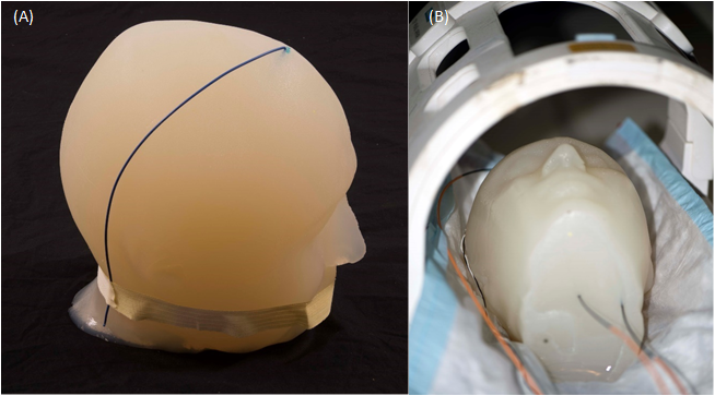
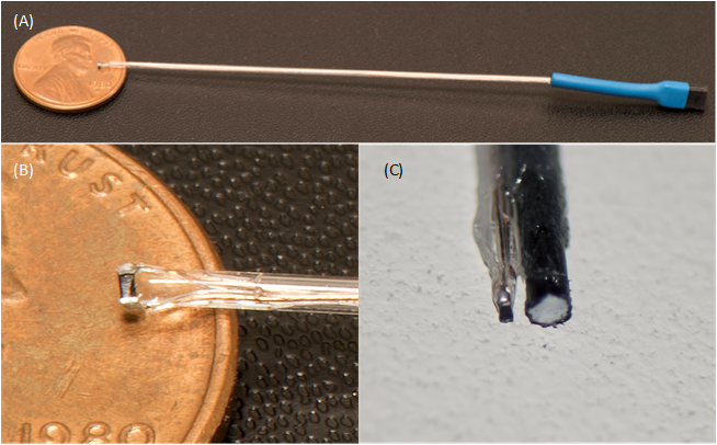
Temperature measurements were performed in a 1.5T Siemens Magnetom Avanto Tim, with an eight-channel transmit-receive coil (Fig.1B) used at the A.A. Martinos Center for the clinical head imaging of patients with implants. Fluoroptic temperature probes (Osensa Innovations Corp., Burnaby, Canada) were used to measure the temperature in close proximity of µMS coils (less than 1mm) and wire albeit not in contact with the implants (Fig.2C). Two implants were studied: a standard copper wire with a 1.5mm exposed tip (Fig.1A) and µMS coil (Fig.2B) designed and manufactured specifically for deep brain stimulation (DBS, Fig.2A). Each of the two implants was placed, in separate MRI sessions, in an anatomically realistic head phantom (Fig.1A) previously described in [7], which is optimized for temperature safety MRI studies.Results.
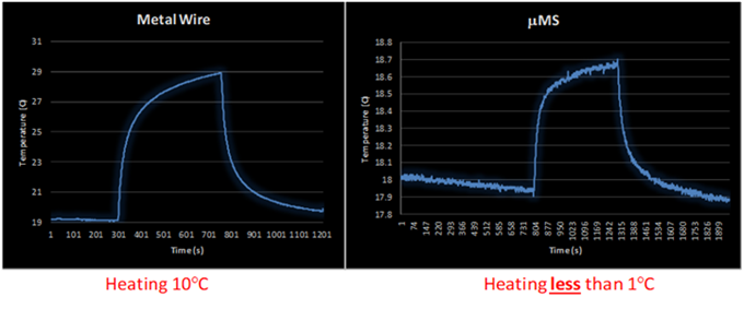
A total of 5 minutes scan with a turbo spin echo sequence (TSE) that was adjusted to provide slightly over 100% SAR generated two different temperature peaks (Fig. 3) for the µMS coil and the copper wire. The copper wire heated with a peak of 10°C above a baseline room temperature of 19°C. However, the µMS coil heating peak was only 0.8°C over baseline, which was higher since the recording was performed immediately after the wire heating scan.Discussion and Conclusions.
A major concern when performing MRI examinations in patients with electrically conductive implants are the induced currents due to the antenna effect [3] along conductive leads in the body that are exposed to the B1 field. This induced current increases the net current flow into the tissue at the point of contact with the lead (i.e., the electrodes), and causes a large amount of RF energy to be absorbed in the tissue, which in turn causes surges in temperatures that can lead to serious injury [3, 8-13]. However, the temperature measured in the proximity of the μMS coil was instead below 1°C and would not produce any thermal damage to the tissue [14].The temperature measurements at 1.5T showed that the exposed tip of the copper wire produced instead an increased temperature of more than 10x greater than the proposed μMS coils. Although these are promising results, it should be noted that direct temperature safety conclusion cannot be made from these temperature measurements results and further temperature measurements and electromagnetic simulations are required to assess MRI compatibility.Acknowledgements
This work was supported by the National Institutes of Health grants R43NS086108 and K99EB021320.References
1. Serano, P., et al., A novel brain stimulation technology provides compatibility with MRI. Sci Rep, 2015. 5: p. 9805.
2. Collins, C.M., et al., Temperature and SAR calculations for a human head within volume and surface coils at 64 and 300 MHz. J Magn Reson Imaging, 2004. 19(5): p. 650-6.
3. Angelone, L.M., et al., Analysis of the role of lead resistivity in specific absorption rate for deep brain stimulator leads at 3T MRI. IEEE Trans Med Imaging, 2010. 29(4): p. 1029-38.
4. Bonmassar, G., et al. Microscopic Magnetic Stimulation. in 10th Vienna International Workshop on Functional Electrical Stimulation. 2010. Vienna, Austria: International FES Society.
5. Bonmassar, G., et al., Microscopic magnetic stimulation of neural tissue. Nat Commun, 2012. 3: p. 921.
6. Park, H.J., et al., Activation of the central nervous system induced by micro-magnetic stimulation. Nat Commun, 2013. 4: p. 2463.
7. Angelone, L.M., et al., On the effect of resistive EEG electrodes and leads during 7 T MRI: simulation and temperature measurement studies. Magn Reson Imaging, 2006. 24(6): p. 801-12.
8. Guy, A., Biophysics-energy absorption and distribution. AGARD Lecture Series, Radiation Hazards (Non-ionizing Radiations--Biological Effects and Safety Considerations, 1975. 78.
9. Buchli, R., P. Boesiger, and D. Meier, Heating effects of metallic implants by MRI examinations. Magn Reson Med, 1988. 7(3): p. 255-61.
10. Chou, C.K., J.A. McDougall, and K.W. Chan, RF heating of implanted spinal fusion stimulator during magnetic resonance imaging. IEEE Trans Biomed Eng, 1997. 44(5): p. 367-73.
11. Angelone, L.M., et al., Metallic electrodes and leads in simultaneous EEG-MRI: specific absorption rate (SAR) simulation studies. Bioelectromagnetics, 2004. 25(4): p. 285-95.
12. Bassen, H., et al., MRI-induced heating of selected thin wire metallic implants-- laboratory and computational studies-- findings and new questions raised. Minim Invasive Ther Allied Technol, 2006. 15(2): p. 76-84.
13. Cabot, E., et al., Evaluation of the RF heating of a generic deep brain stimulator exposed in 1.5 T magnetic resonance scanners. Bioelectromagnetics, 2013. 34(2): p. 104-13.
14. van Rhoon, G.C., et al., CEM43 degrees C thermal dose thresholds: a potential guide for magnetic resonance radiofrequency exposure levels? Eur Radiol, 2013. 23(8): p. 2215-27.
Figures