4050
Optical tracking-guided MR-ARFI for targeting focused ultrasound neuromodulation1Biomedical Engineering, Vanderbilt University, Nashville, TN, United States, 2Vanderbilt University Institute of Imaging Science, Vanderbilt University, Nashville, TN, United States, 3Chemical and Physical Biology, Vanderbilt University, Nashville, TN, United States, 4Radiology and Radiological Sciences, Vanderbilt University Medical Center, Nashville, TN, United States, 5Molecular Physiology and Biophysics, Vanderbilt University, Nashville, TN, United States, 6Physics and Astronomy, Vanderbilt University, Nashville, TN, United States, 7Electrical Engineering and Computer Science, Vanderbilt University, Nashville, TN, United States
Synopsis
Magnetic resonance-acoustic radiation force imaging (MR-ARFI) pulse sequences permit localization and targeting during focused ultrasound (FUS) therapy. MR-ARFI uses motion-encoding gradients (MEGs) to visualize the tissue displacement caused by the acoustic beam’s radiation force. However, a priori knowledge of the acoustic beam’s position and orientation in space is critical for MR-ARFI so that the MEGs can be placed in the proper orientation. We used an optical tracking system to inform the geometry of MR-ARFI acquisitions. The proposed methods will be used to guide ongoing experiments that use MR-ARFI to produce acoustic beam maps for targeting ultrasound neuromodulation in real-time.
Introduction
Magnetic resonance imaging (MRI)-guided focused ultrasound (FUS) has many potential neurological applications.1 MRI guidance during FUS therapy permits localization and targeting of the acoustic beam via MR-acoustic radiation force imaging (MR-ARFI) pulse sequences,2 which use motion-encoding gradients (MEGs) to visualize the tissue displacement caused by the acoustic beam’s radiation force. Due to its micron-scale sensitivity, MR-ARFI is a promising tool for guiding transcranial FUS procedures performed at low acoustic pressures, like neuromodulation. However, a priori knowledge of the acoustic beam’s position and orientation in space is critical for MR-ARFI so that the MEGs can be placed in the proper orientation. In this study, we applied optical tracking to inform the geometry of MR-ARFI acquisitions for image-guided neuromodulation.Methods
Figure 1 illustrates the experimental setup. An MRI-compatible, spherical single-element FUS transducer (Sonic Concepts H115; Sonic Concepts, Washington, USA) was used to sonicate a tissue-mimicking phantom (1% agar/4% graphite). The phantom was rigidly attached to the transducer housing, and the transducer-phantom apparatus was mounted on a plastic tabletop with a three-axis positioning system. In this way, our sonications could be performed in situ in any physical orientation.
Displacement maps were acquired using a spin echo 2D MR-ARFI sequence implemented on a 7 Tesla scanner (Philips Achieva; Philips Healthcare, Best, NL), with parameters: FOV/matrix/voxel size 120x120x2 mm3/60x60x1/2 mm3 isotropic; TE/TR 15/1000 ms; 27° flip angle; multishot EPI readout with 5 shots per TR. A homemade surface coil was used for transmit/receive. Repeated unipolar MEGs were used for ARFI encoding, with gradient duration/strength 3 ms/40 mT$$$\cdot$$$m-1. The second MEG was synchronized with an ultrasound emission using TTL outputs sent to the transducer. Sonications were performed at 802 kHz with a low duty cycle (3609 cycles every TR or 1000 ms; free-field pressure 2.8 MPa). Displacement maps were reconstructed by subtraction of four phase images (ϕON+, ϕON-, ϕOFF+, ϕOFF-) using opposite MEG polarities with FUS turned on or off:3 $$$\frac{ (\phi^{ON+}-\phi^{ON-})-(\phi^{OFF+}-\phi^{OFF-}) }{2 \gamma G \tau}$$$
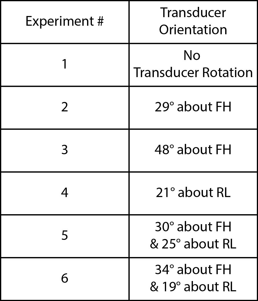
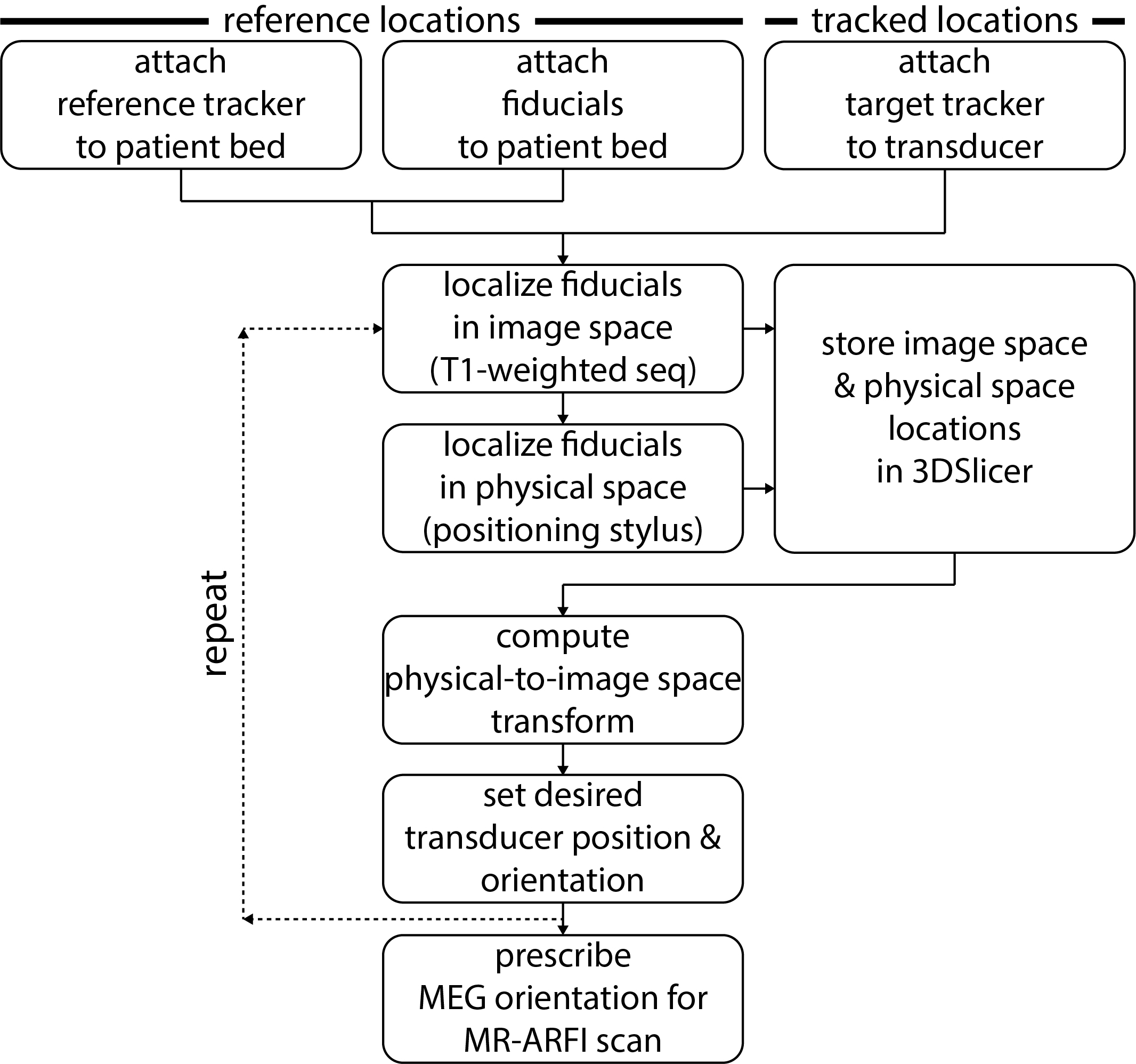
Displacement maps were acquired after rotating the transducer about either the AP (anterior-posterior or $$$\pm x$$$), RL (right-left or $$$\pm y$$$), or FH (foot-head or $$$\pm z$$$) cardinal axes. The transducer was positioned in six orientations (Figure 2). In each case, an optical tracking system (Polaris Vicra; Northern Digital Inc., Ontario, CAN) was used to determine the position and orientation of the transducer. Figure 3 summarizes this workflow. First, an MRI-compatible rigid body tracker was mounted to the patient bed, which served as the global reference location. Another body tracker was mounted to the transducer-phantom apparatus as the tracked location. Multimodality fiducial markers (MM3003; IZI Medical Products, Maryland, USA) were placed around the patient bed. Next, the fiducials were localized in image space using a 3D T1-weighted pulse sequence (voxel size/TE/TR 0.4x0.4x1 mm3/1.9/4 ms). The fiducials were manually identified in the T1-weighted image stack using 3DSlicer.4 Then, in front of the optical tracking camera, the fiducials were localized in physical space using a reflective positioning stylus and recorded in 3DSlicer. These were finally registered to the fiducials’ image locations, yielding a physical-to-image space transform. The phantom could then be freely rotated in physical space, with 3DSlicer reporting the updated slice offset and angulation about each cardinal axis in image space. This information was used to prescribe MEG orientations parallel to the transducer propagation axis to encode maximum displacement. As negative controls, we also acquired three additional displacement maps with MEGs placed along only one cardinal axis.
Results
Figure 4A shows displacement maps from two representative experiments. The observed displacement is highest when MEG orientations are prescribed parallel to the transducer propagation axis via optical tracking. Figure 4B reports the mean focal displacement across all experiments. In all cases, displacement is highest when encoding along the transducer propagation axis, and the values are similar (range = 1.32-1.41 µm).Discussion
These results indicate that knowledge of the acoustic beam’s position and orientation in space is critical for MR-ARFI. In some cases, the observed displacement was completely missed if the MEGs used for ARFI encoding were prescribed in the wrong orientation. The proposed optical tracking workflow will be used to guide ongoing experiments that use MR-ARFI to produce acoustic beam maps for targeting ultrasound neuromodulation in real-time (Figure 5).Conclusion
Optical tracking was successfully used to inform the geometry of MR-ARFI acquisitions. Knowledge of the acoustic beam’s position and orientation in space is critical so that the MEGs used for ARFI encoding can be prescribed in the correct orientation.Acknowledgements
This work was supported by NIH grants R24
MH 109105 and R01 MH 111877.
References
1. Weintraub D, Elias WJ. The emerging role of transcranial magnetic resonance imaging-guided focused ultrasound in functional neurosurgery. Mov Disord. 2017:32(1):20-27.
2. McDannold N, Maier SE. Magnetic resonance acoustic radiation force imaging. Med Phys. 2008:35(8):3748-58.
3. Chen J, Watkins R, Pauly KB. Optimization of encoding gradients for MR-ARFI. Magn Reson Med. 2010:63(4):1050-8.
4. http://www.slicer.org/
Figures
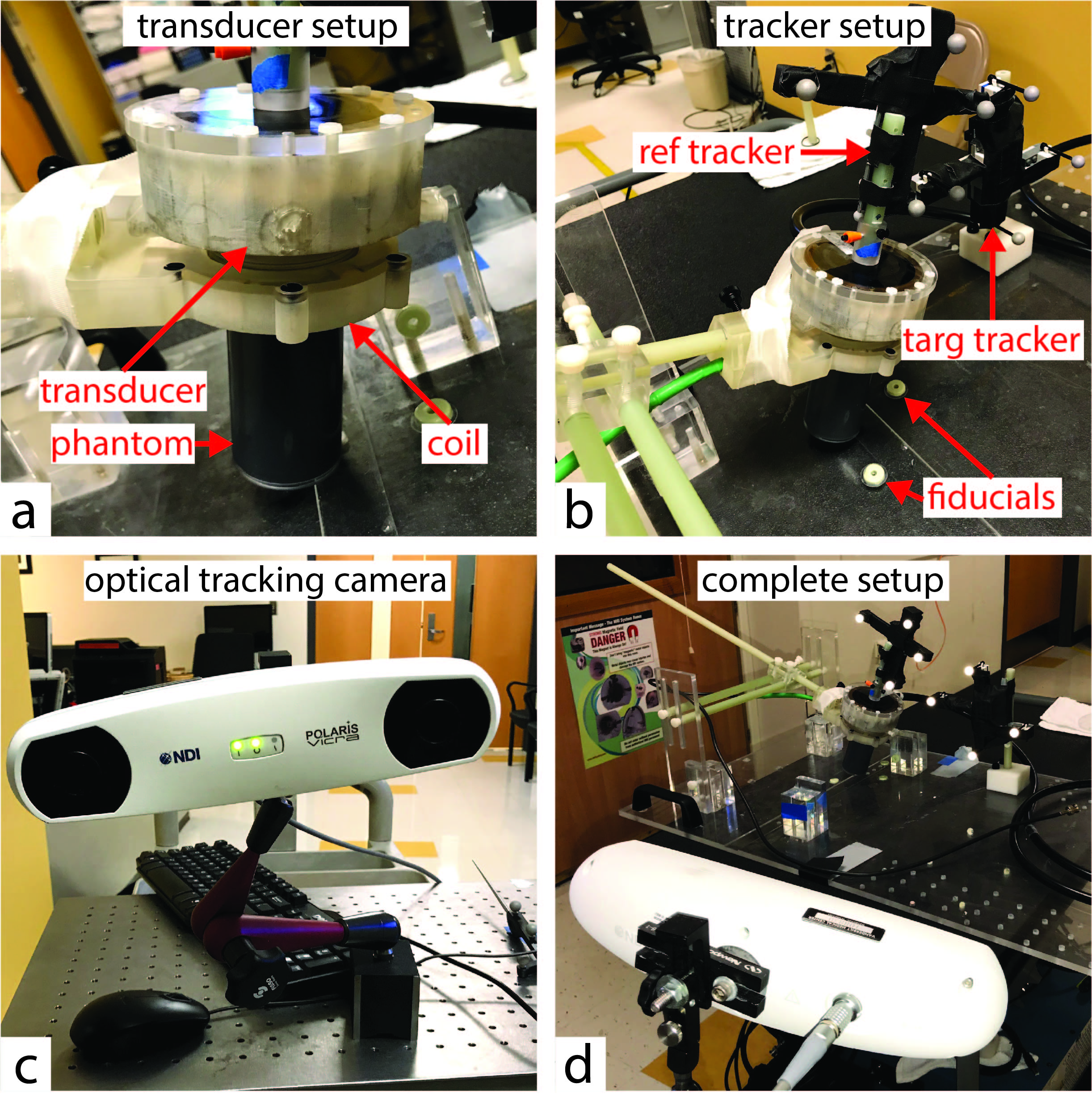
Optical tracking experimental setup.
(A) A tissue-mimicking phantom was rigidly attached to an MRI-compatible, spherical single-element FUS transducer. A homemade surface coil was used for transmit/receive.
(B) A reference tracker and multimodality fiducial markers were mounted to the patient bed. A target tracker was mounted to the transducer-phantom apparatus.
(C) Polaris Vicra optical tracking camera used for this experiment.
(D) The transducer-phantom apparatus was mounted on a plastic tabletop with a three-axis positioning system, in sight of the optical tracking camera. In this way, our sonications could be performed in situ in any physical orientation.

Displacement maps acquired from optical tracking-guided MR-ARFI acquisitions.
(A) Displacement maps from two representative experiments. In both cases, the observed displacement is highest when MEG orientations are prescribed parallel to the transducer propagation axis via optical tracking.
(B) Mean focal displacement across all experiments. In all cases, displacement is highest when encoding along the transducer propagation axis, and the values are similar (range 1.32-1.41 µm). In some cases, the observed displacement was completely missed if the MEGs used for ARFI encoding were prescribed in the wrong orientation. Displacement values were computed in a 3.0 mm2 ROI at the focus.
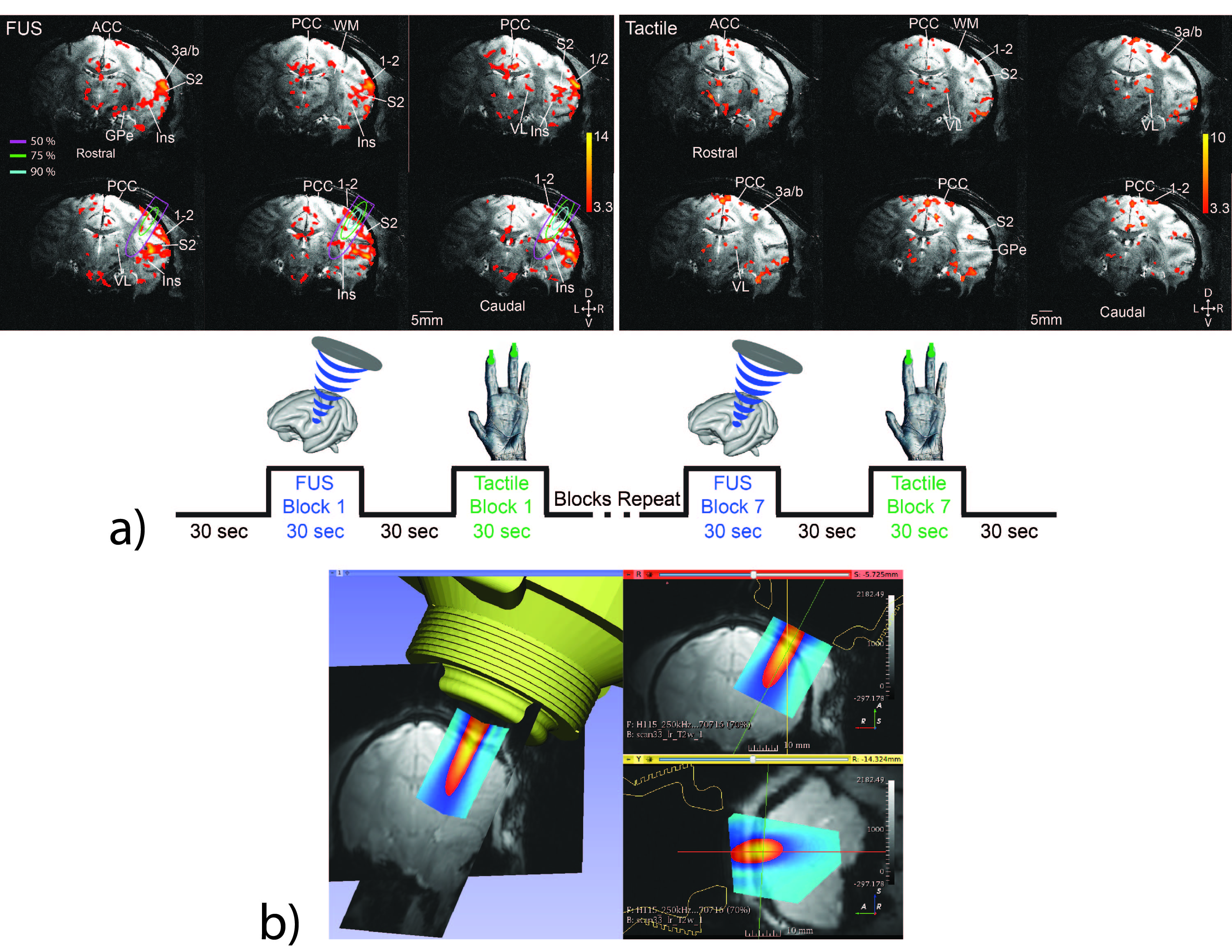
Ongoing experiments in ultrasound neuromodulation.
(A) Our group has shown that MRI-guided FUS is capable of exciting precisely targeted areas 3a/3b in monkey brain, causing downstream activations in off-target but functionally-related brain regions via functional MRI readouts. We observed a similarity between natural tactile stimulation and FUS-elicited fMRI activation patterns, indicating that FUS likely excited areas in functionally-related touch regions.
(B) The proposed optical tracking workflow has already been implemented to overlay free-field acoustic beam maps for targeting ultrasound neuromodulation. In future experiments, the proposed workflow will be used to guide MR-ARFI acquisitions to produce acoustic beam maps for targeting ultrasound neuromodulation in real-time.