3804
Assessment Geometric Distortion in MRI for Gynaecological Brachytherapy Planning at 3T1CR-UK and EPSRC Cancer Imaging Centre, Royal Marsden NHS Foundation Trust & Institute of Cancer Research, Sutton, United Kingdom, 2Radiology, Royal Marsden NHS Foundation Trust, London, United Kingdom, 3Radiotherapy, Royal Marsden NHS Foundation Trust, London, United Kingdom
Synopsis
MRI is increasingly used in radiotherapy treatment planning due to its superior soft tissue contrast. The growing interest in 3T MRI relates to the potential of higher signal-to-noise ratio and spatial resolution. However, geometric distortions associated with magnetic field inhomogeneity increase with field strength and may compromise geometric accuracy. We quantify the geometric distortion in MRI examinations for high dose rate brachytherapy planning for gynaecological cancer at 3T, and consider its clinical impact, taking into account the brachytherapy applicators, the subject’s susceptibility distribution and hardware-related distortions. We found localised areas of field inhomogeneity, and displacements of less than 1mm.
Purpose
To quantify the geometric distortion in MRI examinations for high dose rate brachytherapy planning for gynaecological cancer at 3T, and to consider its clinical impact.Introduction
Magnetic resonance imaging (MRI) is increasingly used in radiotherapy (RT) treatment planning due to its superior soft tissue contrast [1]. For cervix brachytherapy GEC-ESTRO guidelines recommend MRI guided planning following applicator insertion [2]. Typically, MRI for brachytherapy is performed at 1.5T. Geometric distortions associated with magnetic field inhomogeneity increase with field strength and may compromise the geometric accuracy of the examination at 3T[3].
All potential sources of geometric distortion were considered in this study. System-level image distortions were investigated using a structured test object. Field inhomogeneity associated with the brachytherapy applicators at 3T were quantified with the applicators immersed in saline. Furthermore, susceptibility-related field inhomogeneity associated with pelvic structures was quantified by field mapping with the applicator in situ.
Methods
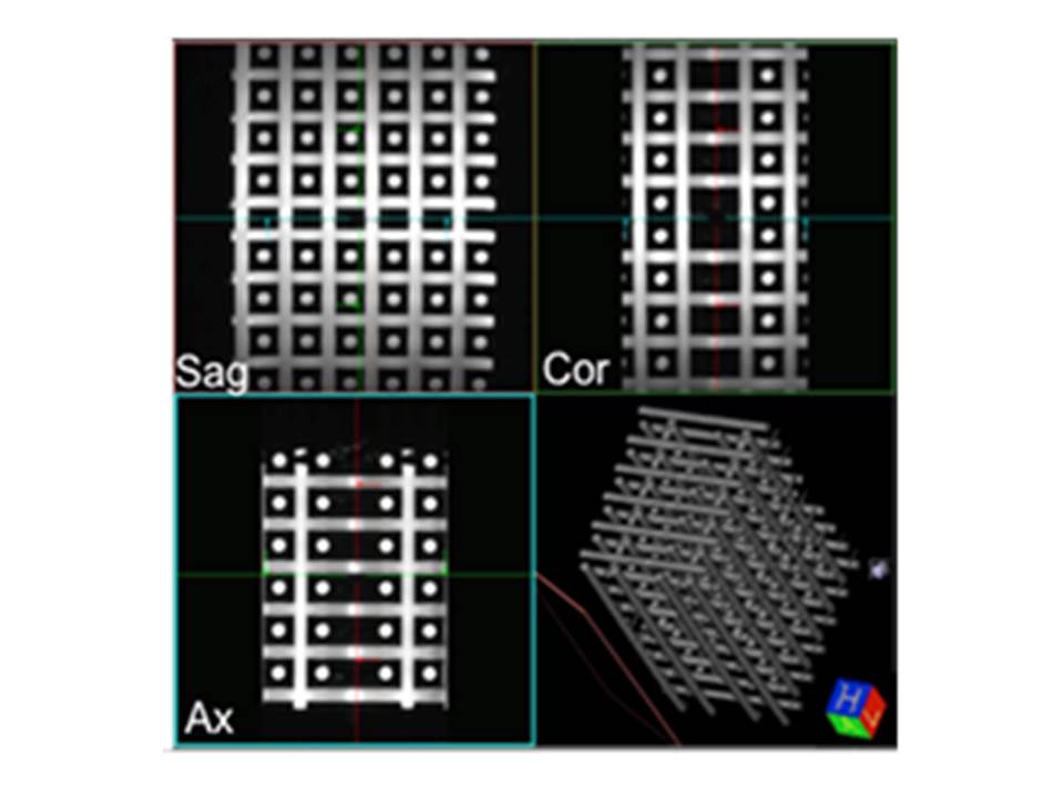
A structured test object (TO) consisting of an array of tubes in three orthogonal directions [4] was scanned using the 3D T2-weighted pulse sequence used in brachytherapy planning (TE=80ms, TR=1340ms, 0.8x0.8x0.8mm3, bandwidth = 505 Hz/pixel), after shimming over the scanned volume. These images were compared to a test object CT, previously acquired (1.07x1.07x1.25 mm3). A second MRI dataset was acquired after inversion of readout and phase encoding gradient to yield information on any distortion associated with susceptibility variations within the test object which could affect the assessment of geometric distortion.
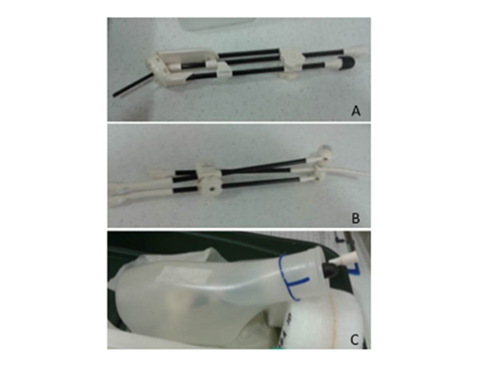
MR-compatible applicators employed in HDR gynaecological brachytherapy were tested (Figure 1). Brachytherapy applicators were scanned immersed in saline, inside a container which kept them approximately in the same position and orientation to the magnetic field used clinically (Figure 1c). Phase images were obtained (TE1/TE2 = 2.46ms/4.92ms) to calculate field maps and evaluate the field inhomogeneity associated with the applicators. This evaluation requires the acquisition of a field map of the container without the applicator, as phase changes are determined by the container shape only.
Phase images were also acquired for patients with the brachytherapy applicators in place to evaluate field inhomogeneity in a clinical situation. The estimated field inhomogeneity values were used to calculate actual displacements which would occur with the brachytherapy 3D T2-w sequences.
Results
Figure 2 shows that for the central portion of the test object all tubes appear straight. Maximum Intensity Projections along the 3 main axes show that any distortion can be estimated as smaller than the pixel size (< 0.8mm) in any direction. Inversion of readout gradient direction demonstrates that some sub-pixel distortions associated with the test object’s own distribution of susceptibilities are measurable, but very small.
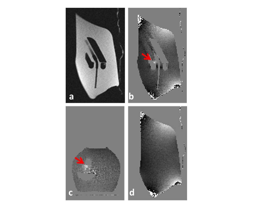
Field Maps calculated around brachytherapy applicators do not appear uniform; this is due in part to the irregular shape of the container (Figure 3d). In all applicator images only one area of localised magnetic field inhomogeneity was detected, reaching 1.8 ppm in the vicinity of the central locking cuff of the tube onto the ring (red arrow, sagittal and transaxial views 3b and 3c). However this portion of the applicator is not clinically relevant.
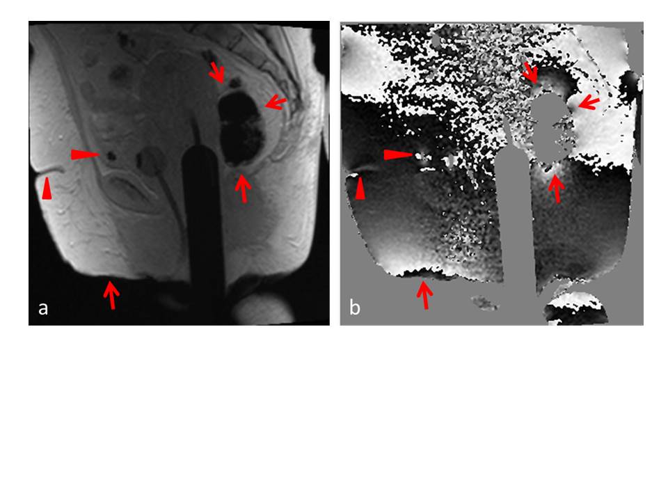
Field maps obtained in patients (Figure 4) show that the localised field inhomogeneity associated with air spaces reaches 4.3±0.1 ppm. Air spaces may occur in the vicinity of the planning target volume, and their shape is unpredictable. This can lead to displacements of up to 0.9 mm with the brachytherapy sequence employed (receiver bandwidth 505 Hz/pixel). In contrast, the expected displacement associated with the applicator is only 0.4 mm. Clinical field maps present a drift in the superior/inferior direction.
Discussion
In gynaecological HDR brachytherapy geometric accuracy is vital for accurate applicator reconstruction and target contouring. The main source of geometric distortion in gynaecological brachytherapy is not hardware, but susceptibility variations within the patient. We found one region of localised field inhomogeneity within one of the applicators. The field inhomogeneity (1.8 ppm) was smaller than that associated with the presence of air within the rectum (4.3 ppm). Due to the inherent variability of the field inhomogeneity associated with the presence of air within the pelvis, displacements of the order of 1 mm can be expected.
This work highlights some of the technical difficulties in mapping field maps clinically. The field maps in Figure 4 are noisy and contain a drift in the superior-inferior direction which may indicate shimming failure and merit further investigation. The results of this study confirm the feasibility of utilising 3T MRI in gynaecological brachytherapy and support the development of MRI-only workflow in this setting.
Acknowledgements
CRUK and EPSRC in association with MRC, NHS funding to the NIHR Biomedicine Research Centre and Clinical Research Facility in Imaging.
References
1.MA Schmidt and GS Payne. Phys Med Biol. 2015 November 21; 60(22): R323–R361.
2.JC Dimopoulos et al. Radiother Oncol. 2012; 103:113–22.
3.AAC. De Leeuw et al. Radiother Oncol, 2009; 93: 341-346
4.SJ Doran et al. Phys Med Biol, 2005; 50, 1343-61.
Figures