3698
Integrated B1+ Mapping for Hyperpolarized 13C MRI in a Clinical Setup using Multi-Channel Receive Arrays1Department of Electrical Engineering, Technical University of Denmark, Kgs. Lyngby, Denmark, 2Department of Radiology and Biomedical Imaging, UCSF, San Francisco, CA, United States
Synopsis
For hyperpolarized 13C MRI acquisitions aimed at metabolic rate constant estimation, the Bloch-Siegert shift enables encoding of the transmit field (B1+-field) amplitude within a single hyperpolarized substrate injection. This ability is needed since most clinical hyperpolarized MRI studies use inhomogeneous transmit coils, and because kinetic modeling based on incorrect flip angles can lead to incorrect rate constant estimations. This study demonstrates the feasibility of integrated B1+ mapping for large volume thermal and hyperpolarized phantoms in a clinical setup using a clamshell transmit coil and a 16-channel receive array, and a 3D stack-of-spirals sequence. Phase-sensitive coil-combination was achieved using ESPIRiT.
Introduction
By means of the Bloch-Siegert shift, the transmit field (B1+) amplitude can be encoded into the signal phase during MRI acquisition.1 For hyperpolarized carbon-13 MRI, this can provide data that enable B1+-field mapping together with spatial mapping of metabolic rate constants within one hyperpolarized substrate injection.2 Integrated B1+ mapping is motivated by an extensive use of inhomogeneous clamshell-type transmit coils3 in clinical hyperpolarized MRI applications,4–6 together with reduced quantitation accuracy of rate constants when modeling with incorrect flip angles.7 While proof-of-principle integration of Bloch-Siegert B1+ mapping in a hyperpolarized study has been shown,2 this study focuses on a clinical setup using multi-channel arrays that enable parallel imaging for acquisition acceleration. However, for phase-based B1+ mapping methods, phase-sensitive coil-combination is a challenge. By using ESPIRiT8 for coil-combination, SNR-levels comparable to using sum-of-squares can be achieved, while preserving phase information.Methods
Bloch-Siegert B1+ mapping was integrated in a 3D stack-of-spirals sequence with singleband spectral-spatial (SPSP) excitation. By alternating between positive and negative off-resonance Bloch-Siegert pulses through the full dynamic acquisition, B1+ mapping is possible across multiple time points. This makes the method robust against spatially varying signal support over time; expected in vivo.
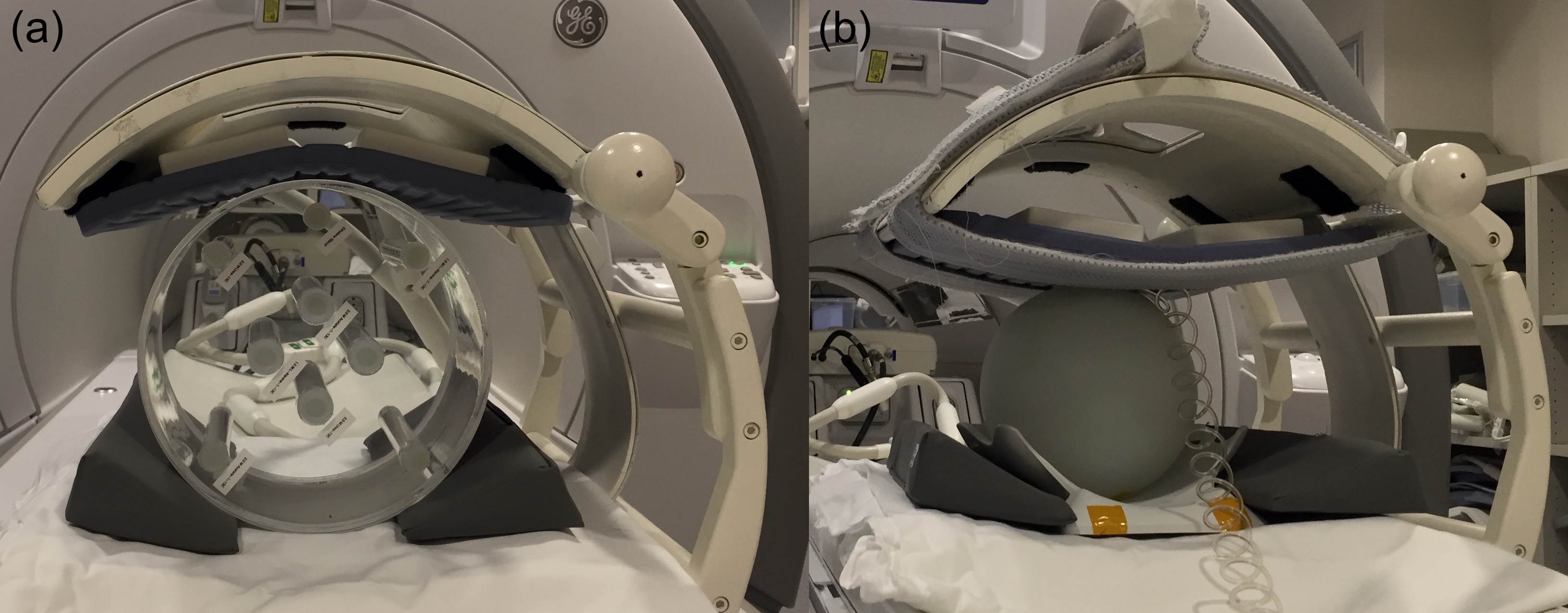
All data were acquired on an MR750 3T scanner (GE Healthcare, Waukesha, WI, USA) with a 13C clamshell coil for excitation and a 16-channel coil for reception (Rapid Biomedical, Rimpar, Germany). See coil setup in Figure 1.
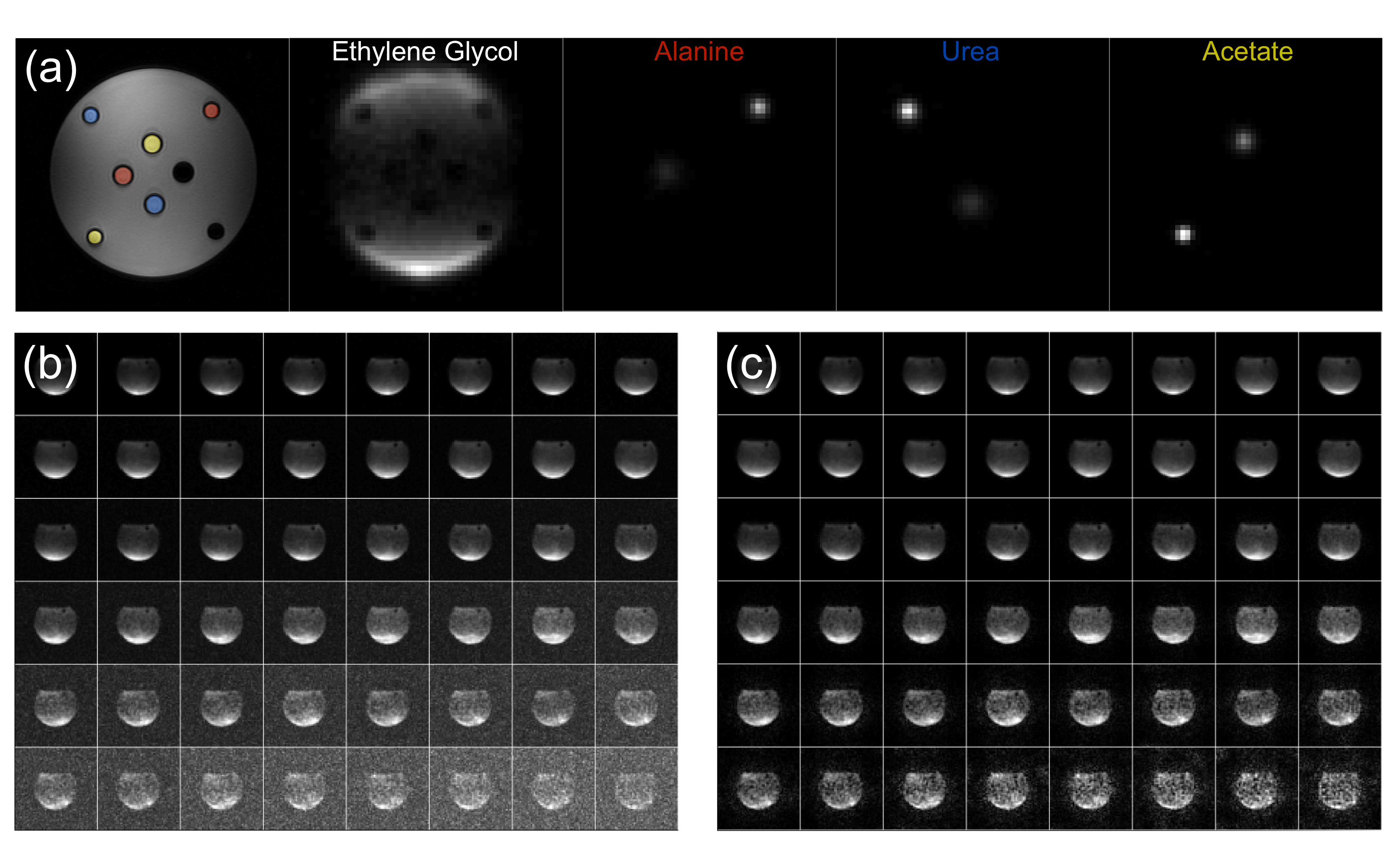
Multi-compartment thermal phantom: Image data were acquired for a 32x32x12 cm3 FOV with a 30-ms single-shot-spiral readout in the axial plane and 10 phase-encodes (superior/inferior). Two measurements were conducted with 4-ms Bloch-Siegert pulses applied +/-2 kHz off-resonance. Other scan parameters: TR 1 s; flip angle 70°; NEX 32; SPSP frequencies four (Ethylene Glycol, Urea, Alanine, Acetate (∆f = [0,3177,3598,3803] Hz)). The spirals were gridded to a 54x54 matrix and filtered to result in an isotropic resolution of 1.2 cm. The data were coil-combined using ESPIRiT for each 3D volume, across frequencies and time points, before estimating B1+ maps as previously described.1
Hyperpolarized [1-13C]pyruvate phantom: 1.47 g of [1-13C]pyruvic acid doped with 15 mM electron paramagnetic agent was polarized for 3 hours in a 5T Spinlab at 0.78 K. The sample was rapidly dissolved and neutralized yielding 42 mL pyruvate (259 mM, 44 % polarization). This was added to a sphere containing ~2.5 L water. Imaging started 43 s after injection. The sequence was run three times with 16 time points for each run and a 20-s and 10-s delay between runs. Other scan parameters: TR 200 ms; flip angle 5°. FOV, spiral, Bloch-Siegert pulse, and reconstruction method were identical to those for the thermal phantom experiment. Due to long relaxation times and the short TR, the measured signal depends critically on T1, T2, B1 and B0, so fitting of the measured signal to a signal equation was not attempted. This could have provided validation for the B1+ maps.
Results and Discussion
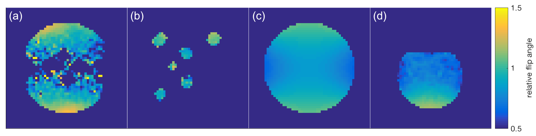
Figure 2(b-c) illustrate how coil-combination by ESPIRiT results in similar or higher SNR levels compared to sum-of-squares reconstruction. Figure 3 shows the B1+ mapping results together with a simulated B1+-field for the clamshell transmitter. All maps show the same pattern. The slightly smaller inhomogeneity of the simulated map compared to the Bloch-Siegert maps is likely explained by a geometry symmetry assumption for the simulation, while the B1+ field of the clamshell coil has experimentally been shown to be asymmetric as visible in Figure 3(a).
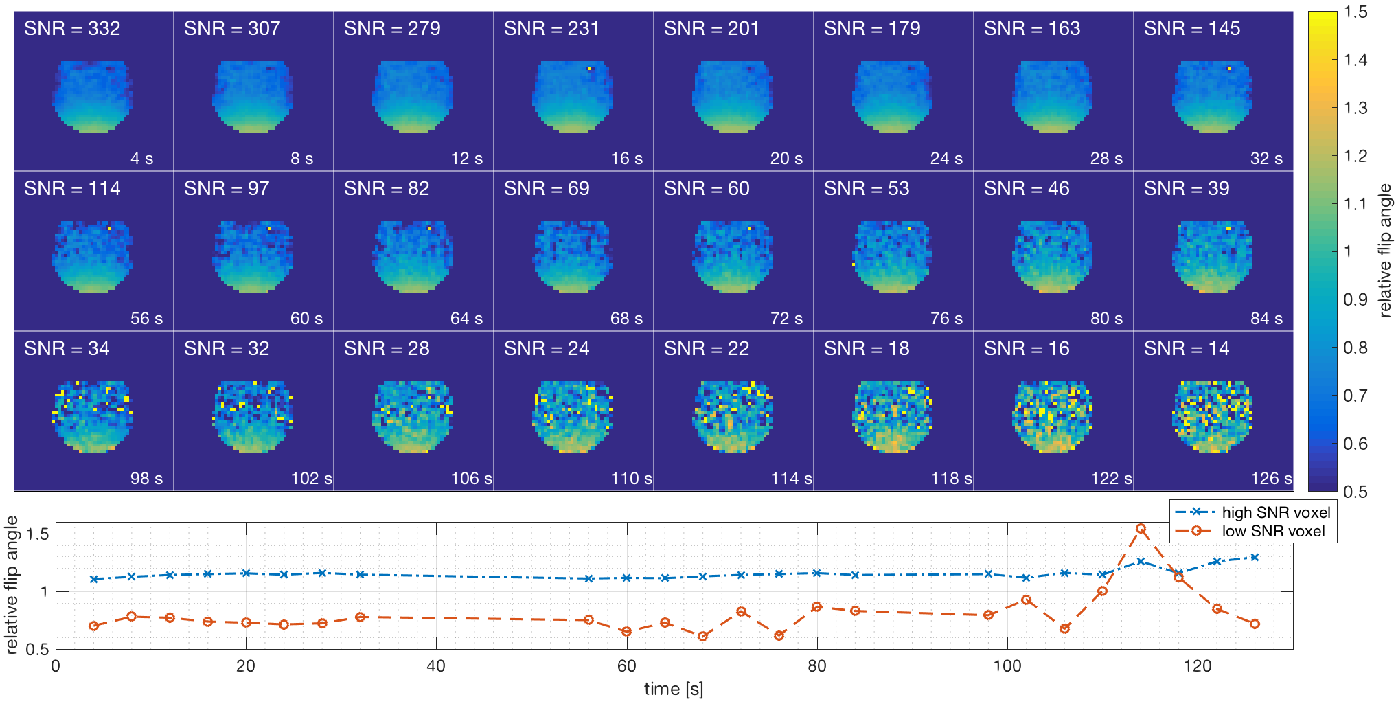
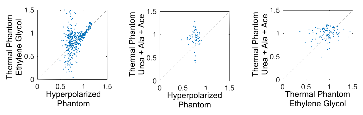
Figure 4 shows 24 B1+ maps extracted from the 24 pairs of consecutive time points of the hyperpolarized experiment. Ideally these would be identical, but as SNR decreases so does reliability of B1+ mapping. In the higher SNR region, flip angles were estimated consistently up to 100 s after acquisition start (70 s active scan time), while in low SNR regions estimates became less consistent after 40 s active scan time. A minimum SNR of ~40 is needed for accurate B1+ estimation. Figure 5 shows scatter plots for the voxel-wise relative flip angle values across experiments. A higher linear correlation was observed for high relative flip angle voxels compared to voxels with low relative flip angle; as these voxels also had low SNR, this is not unexpected.
Conclusion
This study demonstrated feasibility of integrated B1+ mapping for a clinical hyperpolarized 13C coil setup, by means of the Bloch-Siegert shift and ESPIRiT for coil-combination. Future studies should optimize the Bloch-Siegert pulse design to avoid SAR issues, test integration of B1+ mapping in other sequences, validate the results in vivo, and test integrated B1+ mapping with parallel imaging to fully utilize multi-channel receive coils.Acknowledgements
This work has been partly funded by the Independent Research Fund Denmark (DFF – 4005-00531), the Danish National Research Foundation (DNRF124), and the Elite Research travel grant (6161-00043B).References
1. Sacolick, L. I., Wiesinger, F., Hancu, I. & Vogel, M. W. B1 mapping by Bloch-Siegert shift. Magn. Reson. Med. 63, 1315–1322 (2010).
2. Lau, A. Z., Chen, A. P. & Cunningham, C. H. Integrated Bloch-Siegert B1 mapping and multislice imaging of hyperpolarized 13C pyruvate and bicarbonate in the heart. Magn. Reson. Med. 67, 62–71 (2012).
3. Tropp, J. et al. Multi-channel metabolic imaging, with SENSE reconstruction, of hyperpolarized [1-13C] pyruvate in a live rat at 3.0 tesla on a clinical MR scanner. J. Magn. Reson. 208, 171–177 (2011).
4. Cunningham, C. H. et al. Hyperpolarized 13C Metabolic MRI of the Human Heart: Initial Experience. Circ. Res. 119, 1177–1182 (2016).
5. Park, I. et al. Dynamic Hyperpolarized 13C Metabolic Imaging of Patients with Brain Tumors. in Proc. Intl. Soc. Mag. Reson. Med. 555 (2017).
6. Gordon, J. W. et al. Human Hyperpolarized C-13 MRI Using a Novel Echo-Planar Imaging (EPI) Approach. in Proc. Intl. Soc. Mag. Reson. Med. 728 (2017).
7. Chen, H.-Y. et al. Phase II Clinical Hyperpolarized 13C 3D-Dynamic Metabolic Imaging of Prostate Cancer using a B1-insensitive Variable Flip Angle Design. in Proc. Intl. Soc. Mag. Reson. Med. 725 (2017).
8. Uecker, M. et al. ESPIRiT - An eigenvalue approach to autocalibrating parallel MRI: Where SENSE meets GRAPPA. Magn. Reson. Med. 71, 990–1001 (2014).
Figures