3682
PETcoil: Elements of an RF-penetrable positron emission tomography insert for simultaneous PET/MRI1Radiology, Stanford University, Stanford, CA, United States, 2Mechanical Engineering, Stanford University, Stanford, CA, United States, 3Applied Physics, Stanford University, Stanford, CA, United States, 4Electrical Engineering, Stanford University, Stanford, CA, United States, 5Physics, Stanford University, Stanford, CA, United States, 6Bioengineering, Stanford University, Stanford, CA, United States
Synopsis
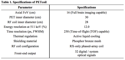
A PET insert dedicated to brain PET/MRI offers several advantages compared to the commercial integrated whole-body PET/MRI systems, including better sensitivity, spatial resolution, and significantly lower price. We are developing an RF-penetrable PET insert integrated with a custom RX-only phased-array coil, termed collectively as “PETcoil”, dedicated for brain PET/MRI (30 cm diameter, 16 cm axial FOV). In this presentation, we will present the design and preliminary results of the PETcoil with regards to minimizing mutual interference between the PET and MRI while maintaining excellent performance.
Introduction
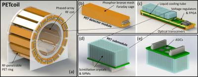
Simultaneous PET/MRI allows the acquisition of anatomical, functional, and molecular information of a patient’s diseases in one imaging session [1]. An MRI-compatible PET insert offers advantages compared to commercial integrated whole-body PET/MRI systems [2-4], including significantly reduced price as users only need to procure the PET insert instead of an integrated PET+MRI system [5]. We are developing an RF-penetrable PET insert with an RX-only phased-array coil (“PETcoil”) (Fig. 1). In this work, we will present the design and initial results of this new PET+RF coil insert.Methods
A. System design
Fig. 2(a) shows the design of the PETcoil consisting of a ring of 16 PET detector modules and an 8-channel phased-array RF coil placed just inside the PET ring inner diameter. Liquid cooling is implemented by attaching cooling bars to the ASIC Chips (Fig. 2(c)). Each submodule consists of an 8×16 array of 3.2×3.2×20 mm3 LYSO crystals one-to-one coupled to an 8×16 array of SiPM pixels (Fig. 2(d)). Four PETA6 ASICs [6] are placed on the back side of the submodule board to read out the signals from the SiPMs. The submodules are connected to the main PCB consisting of power regulation components (Fig. 2(c)), an FPGA chip for controlling and collecting data from the submodules, and optical transceivers for communicating with the data acquisition and synchronization system.
B. Low eddy current Faraday cage
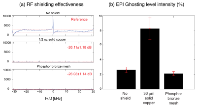
While the main purpose of Faraday cages is to shield the PET detectors from the strong RF fields from the MR system, the rapidly switching gradient fields can induce eddy currents on the conductive shielding cages. ½ oz solid copper and a phosphor bronze mesh Faraday cages were investigated in both the RF shielding effectiveness and the gradient-induced EPI ghosting artifacts.
C. RX-only phased-array coil
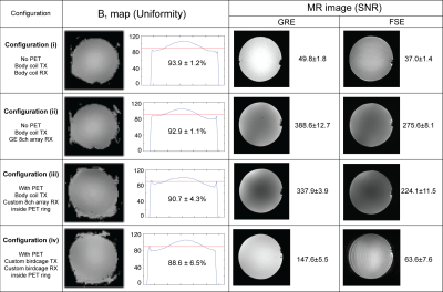
To utilize the RF-penetrability of the PETcoil, allowing the use of the body coil for RF transmission, a RX-only phased-array coil was developed and its performance was analyzed. Its performance was compared with a custom TX/RX birdcage coil placed within the PET insert, which is used in most other PET inserts for PET/MR. The MR performance, including the B1 field uniformity and the MR image SNR comparison, was analyzed.
D. PET coincidence timing resolution (CTR) measurements
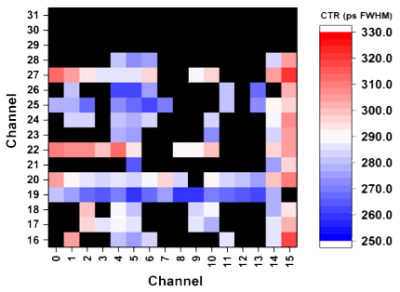
Preliminary coincidence measurements have been performed with two 4×4 LYSO crystal arrays one-to-one coupled to SiPMs and read out by a single PETA6 chip. A 68Ge point source of 500 µm diameter was used for acquiring the coincidences. Air cooling instead of liquid cooling was applied in this setup.
Results and Discussion
A. Low eddy current Faraday cage
Both the ½ oz solid copper and a phosphor bronze mesh Faraday cages showed comparable RF shielding effectiveness (Fig. 3(a)), while the phosphor bronze mesh showed significantly less ghosting level intensity from the induced eddy current compared to the solid copper cage (Fig. 3(b)).
B. RX-only phased-array coil
As expected, the SNR of the MR images acquired with the body coil as the RF transmitter and receiver (configuration (i)) performed the worst due to low receive sensitivity (Fig. 4). The custom RX-only phased array coil with the body coil as the RF transmitter (configuration (iii)) performed significantly better (comparable B1 field uniformity and 128.9±6.6% and 252.4±37.1% higher SNR for GRE and FSE sequences, respectively) than the TX/RX birdcage coil (configuration (iv)). However, configuration (iii)’s SNR was 13.0±3.4% and 18.7±5.1% lower compared to the typical MR-only configuration (configuration (ii)), most likely due to the commercial coil of configuration (ii) being built with optimized materials and high-end components.
C. PET CTR measurements
A CTR of 285 ps FWHM has been achieved in a preliminary measurement with two 4×4 crystal arrays running in coincidence (Fig. 5). This measurement can be improved as the experimental temperature was slightly above the ambient temperature without active cooling, in addition, the trace length between the SiPMs and the PETA6 chips was not optimized in the prototype setup. The 250 ps FWHM CTR goal for this system will provide an image SNR gain of 2 compared to the non-TOF system for a 15 cm diameter head geometry by measuring the TOF information, which will help to further enhance visualization and quantification of brain PET images.
Conclusion
An RF-penetrable PET insert (“PETcoil”) for brain PET/MRI is under-development; The phosphor bronze mesh Faraday cage showed high shielding effectiveness with low eddy current induced artifacts and the phased-array coil performed significantly better in MR performance compared to typical TX/RX birdcage coils used in standard PET inserts for PET/MR. The PET detector achieved a CTR of 285 ps FWHM in preliminary measurements.Acknowledgements
This work was funded in part by an NIH-NIBIB Grant R01-EB01946501 and F31-EB020504.References
[1] H. Barthel, M. L. Schroeter, K.-T. Hoffmann, and O. Sabri, “PET/MR in Dementia and Other Neurodegenerative Diseases,” Seminars in Nuclear Medicine, vol. 45, no. 3, pp. 224–233, May 2015. [Online]. Available: http://www.sciencedirect.com/science/article/pii/S0001299814001469
[2] Delso G, Furst S, Jakoby B, Ladebeck R, Ganter C, Nekolla SG, Schwaiger M, Ziegler SI. Performance measurements of the Siemens mMR integrated whole-body PET/MR scanner. J Nucl Med 2011;52(12):1914-22.
[3] Grant AM, Deller TW, Khalighi MM, Maramraju SH, Delso G, Levin CS. NEMA NU 2-2012 performance studies for the SiPM-based ToF-PET component of the GE SIGNA PET/MR system. Medical Physics 2016;43(5):2334-2343.
[4] Levin CS, Maramraju SH, Khalighi MM, Deller TW, Delso G, Jansen F. Design Features and Mutual Compatibility Studies of the Time-of-Flight PET Capable GE SIGNA PET/MR System. IEEE Transactions on Medical Imaging 2016;35(8):1907-1914.
[5] Vandenberghe S, Marsden PK, PET-MRI: a review of challenges and solution in the development of integrated multimodality imaging. Physics in Medicine & Biology 2015; 60(4) R115-54
[6] I. Sacco, R. Dohle, P. Fischer, C. Piemonte, and M. Ritzert, “A compact, high-density gamma-detection module for Time-of-Flight measurements in PET applications,” Nuclear Instruments and Methods in Physics Research Section A: Accelerators, Spectrometers, Detectors and Associated Equipment, vol. 824, pp. 233–236, Jul. 2016.
Figures
