3565
Comparison between 8- and 32-channel phased-array receive coils for in vivo hyperpolarized C-13 brain imaging1Radiology and Biomedical Imaging, University of California, San Francisco, San Francisco, CA, United States, 2Department of Radiology, Chonam National University Medical School and Hospital, Chonam, Republic of Korea, 3Department of Neurosurgery, University of California, San Francisco, San Francisco, CA, United States, 4Bioengineering and Therapeutic Sciences, University of California, San Francisco, San Francisco, CA, United States
Synopsis
This study sought to evaluate the performance of the first 32-channel head coil for in vivo hyperpolarized 13C brain imaging by comparison against a conventional 8-channel receiver array. Initial phantom experiments characterized the B1+ homogeneity and SNR profiles associated with each hardware configuration via EPI-based imaging techniques. As part of a clinical trial, in vivo dynamic EPI data were also acquired from patients with brain tumors. Phantom and patient data revealed improved uniformity, coverage, and SNR with the 32-channel array that will promote higher resolution and acceleration. In vivo data also demonstrated unprecedented detection of bicarbonate using both hardware platforms.
Introduction
Validating the clinical
utility of hyperpolarized 13C neural imaging is key to understanding its potential diagnostic
impact. Due to the critical role played by RF hardware in carbon imaging,
this study aimed to compare hardware design performance using phantom
experiments and provide a baseline measurement for clinical trial patient data.Methods
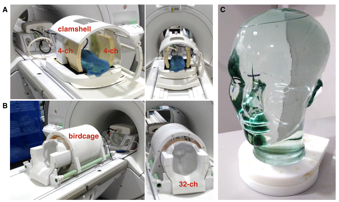
Hardware. All experiments were performed on a clinical 3T whole body scanner (MR 750; GE Healthcare) that was equipped with 32-channel multi-nuclear imaging capability. Investigation focused on characterizing two custom-designed RF hardware configurations for carbon imaging: (1) 8-channel bilateral paddle coils/clamshell transmitter1,2; and (2) the first 13C 32-channel head coil with integrated birdcage transmitter3 (Figure 1). Both receiver assemblies had been tuned and matched at 32.12 MHz for carbon and featured proton blocking at 127.6 MHz; -20dB decoupling. Dynamic disabling of the receiver pathways was accomplished via forward/reverse biasing=2.5/590, 2.0/260 VDC (8,32-channel).
Phantom Calibration. A head-shaped phantom containing unenriched ethylene glycol (99.8%, Sigma Aldrich) sufficiently simulated head morphology for the purposes of maintaining in vivo hardware configurations and evaluating their performance over representative spatial regions. In the case of the clamshell/8-channel assembly, the phantom was positioned within the R-L/S-I isocenter of the transmitter, and the paddle coils were placed on either side, separated by 19 cm to mimic the 32-channel housing. The fixed geometry of the 32-channel receiver array in relation to the birdcage transmitter ensured consistent positioning of the phantom. Using the 1H body coil, a T2-weighted FSE was acquired as an anatomical reference. A FID-CSI sequence with non-slice selective 180o pulse (GE Healthcare) allowed for RF power (TG) calibration, determination of center frequency, and evaluation of linear shimming.
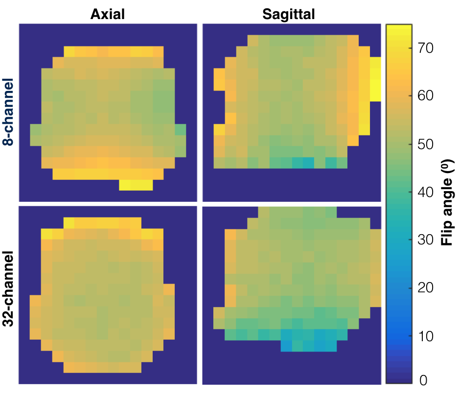
B1+ mapping. Comparisons of hardware performance utilized variants of an echo-planar imaging (EPI) sequence with ramp-sampled, symmetric readout4. In order to correct for EPI distortion arising from phase errors, a reference scan was first acquired with phase-encoding gradients disabled. Empirically characterizing the B1+ field generated by the transmitters entailed 2D imaging of the phantom using a single-band spectral-spatial excitation pulse (130 Hz FWHM, 868 Hz stopband), TR/TE=3000/24.1 ms, echo-spacing=1.33 ms, 1.2x1.2 cm2 in-plane resolution (20x20 cm2 FOV, 16x16 matrix), ±7.58 kHz readout bandwidth, and 5 cm slice thickness. Axial and sagittal slices of the phantom were acquired along the magnetic iso-center with flip angles α=60o and 2α=120o (100 averages each), such that B1+ maps could be calculated according to the double angle method5.
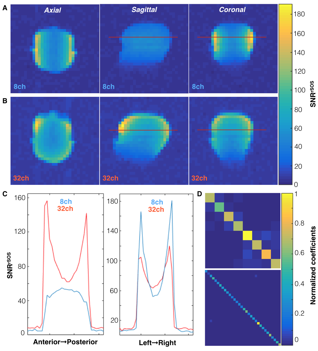
SNR Characterization. Coil sensitivity maps were obtained using a 3D stack-of-EPI variant of the EPI sequence (α=20o, TR/TE=1500/21.7 ms, echo-spacing=0.528 ms, 1 cm isotropic resolution (32x32cm2 FOV, 32x32 matrix), ±167kHz readout bandwidth, 7 timeframes, 400 NEX, 70 min.). Noise data were acquired separately with no transmit RF power. Complex data were summed over timeframes and pre-whitened via Cholesky decomposition of the noise covariance matrices6. Images were reconstructed in SNR units using root sum-of-squares (rSOS)7,8, with noise evaluated on empty-space data.
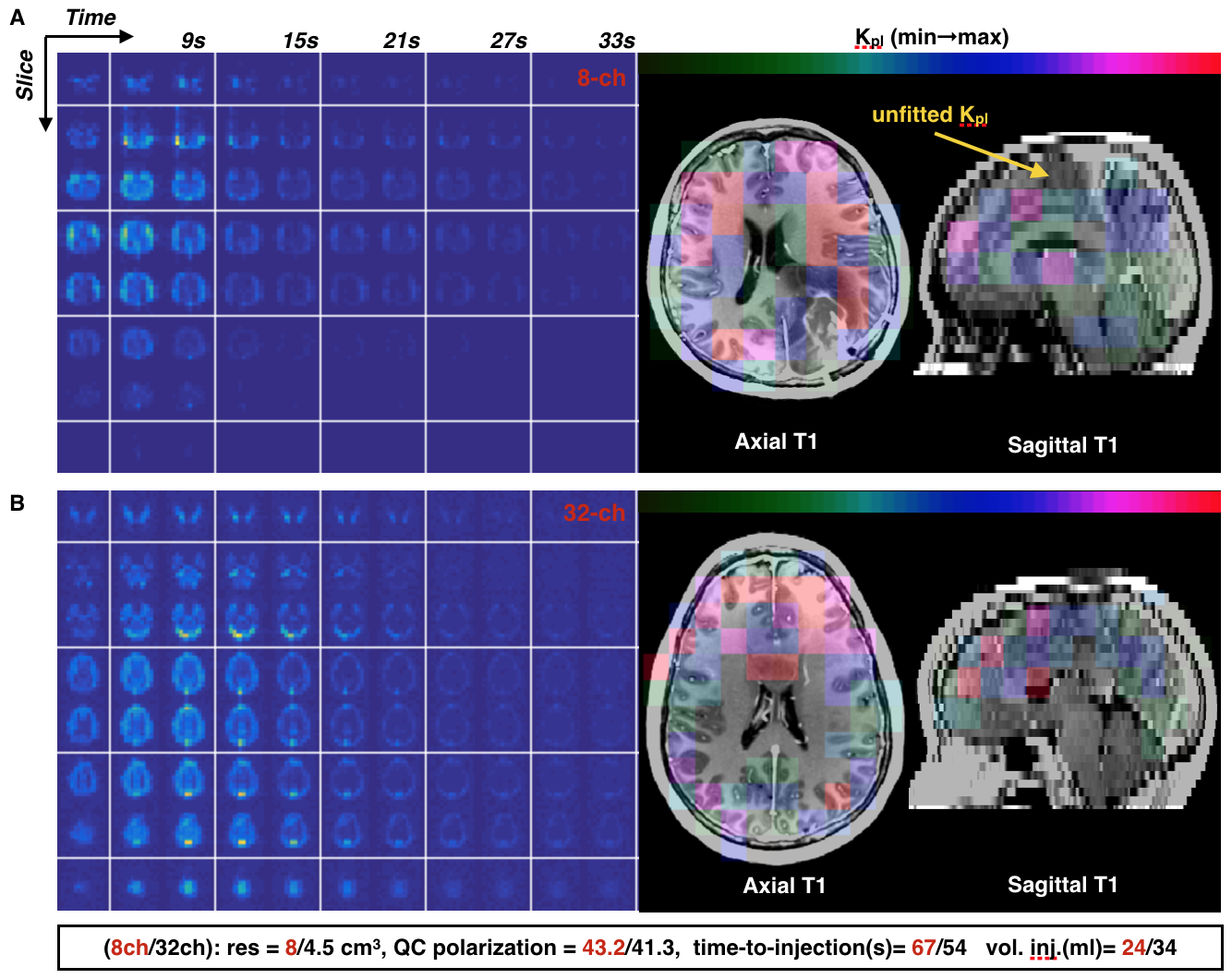
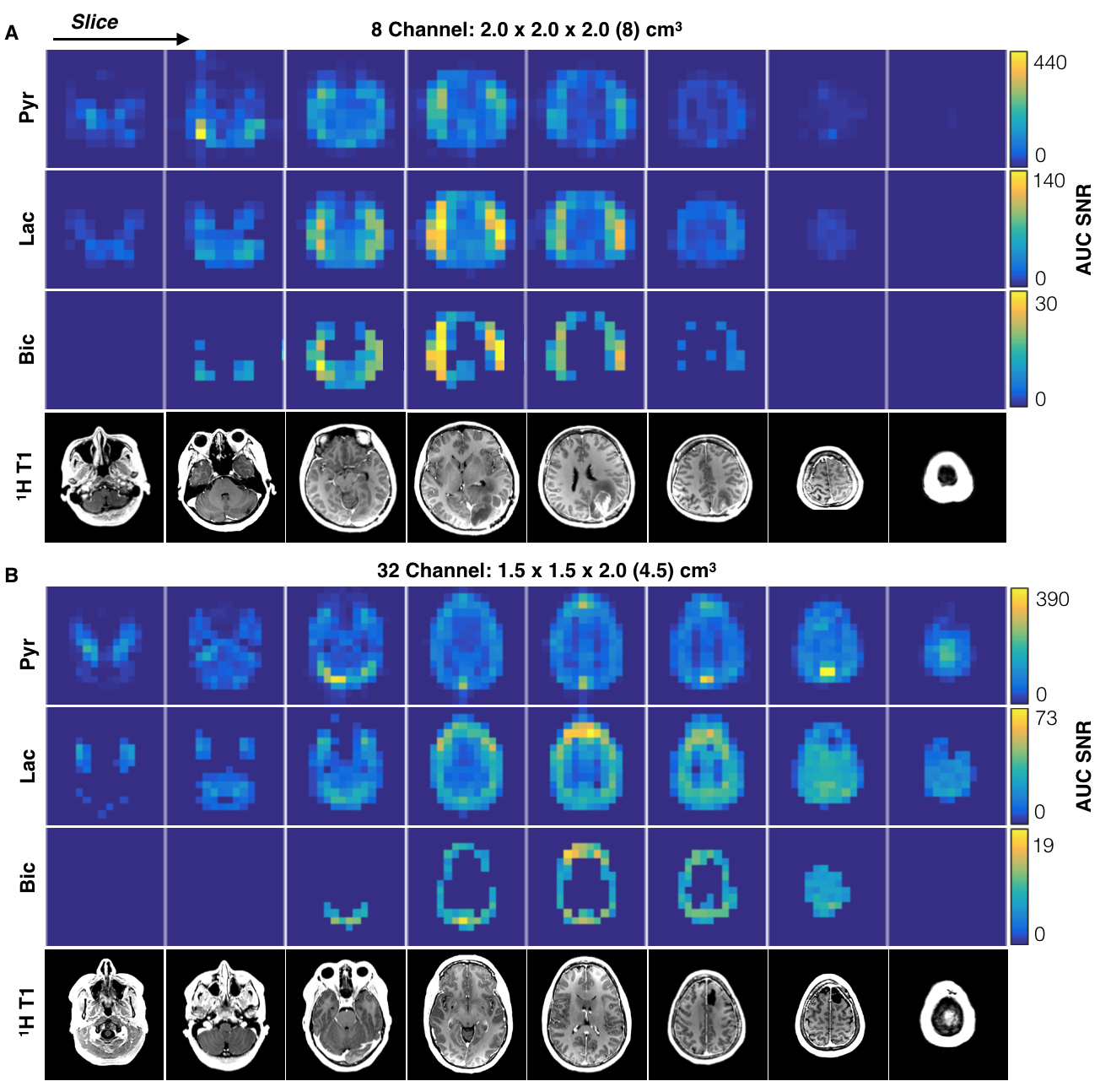
In vivo Imaging. Dynamic hyperpolarized 13C data from 2D multislice EPI (TR/TE=62.5ms/21.7ms, 3 frequencies, αpyruvate/αlactate/αbicarbonate=20o/30o/30o, eight 2cm slices, 20 timepoints, 3s temporal resolution) were acquired from two patients with glioma for both hardware configurations. TGs were calibrated as above using the head phantom and small urea samples provided in vivo frequency referencing. Polarization of [1-13C]-labeled pyruvate was performed on a GE SPINlab system as previously described9. Data were pre-whitened and Kpl and AUC SNR computed.
Results
B1+ maps for each hardware configuration are shown in Figure 2. The central planes of the SNRrSOS maps are displayed with line profiles and normalized noise covariance matrices (Figure 3). Figures 4-5 present the qualitative comparison for dynamic/AUC in vivo patient data.Discussion
The greater B1+ homogeneity demonstrated by the birdcage over the clamshell transmitter is in line with expectations for a volume coil. With regard to reception profiles, the 32-channel receiver array attained 17-24% SNR enhancement in the brain center compared to the 8-channel array, as well as augmented coverage/SNR of regions corresponding to the apical cortex/forebrain/posterior, while displaying greater uniformity. The 8-channel coil predictably showed the highest SNR on the superficial lateral aspects, but it is important to note the difference in loading between patient and phantom studies and improved acceleration potential with the 32-channel array. Although acquired at different resolutions and polarization levels, patient data support greater coverage with the 32-channel headcoil and improved cortical dynamic modeling capability for Kpl. Both hardware configurations detected unprecedented levels of bicarbonate in vivo using EPI.Conclusion
The first 32-channel 13C brain coil offered appreciable SNR gains and signal uniformity over 8-channel hardware that can improve the resolution of in vivo hyperpolarized patient studies.Acknowledgements
This research was supported by NIH grants P01 CA118816 and P41 EB0341598.References
1. Ohliger MA, Larson PE, Bok RA, Shin P, Hu S, Tropp J, et al. Combined parallel and partial fourier MR reconstruction for accelerated 8-channel hyperpolarized carbon-13 in vivo magnetic resonance Spectroscopic imaging (MRSI). J Magn Reson Imaging. 2013;38(3):701-13.
2. Tropp J, Lupo JM, Chen A, Calderon P, McCune D, Grafendorfer T, et al. Multi-channel metabolic imaging, with SENSE reconstruction, of hyperpolarized [1-13C] pyruvate in a live rat at 3.0 tesla on a clinical MR scanner. Journal of magnetic resonance. J Magn Reson. 2011; 208(1): 171–177.
3. Maryem Azema, Lucas Carvajal, Duan Xu, Jeremy Gordon, Ilwoo Park, Daniel B Vigneron, Sarah J Nelson, Jason P Stockmann, Boris Keil, and Lawrence L Wald. 31-Channel Brain Array for Hyperpolarized 13C Imaging at 3T. ISMRM 2017 Abstract#1225.
4. Jeremy W. Gordon, Daniel B. Vigneron, and Peder E.Z. Larson. Development of a Symmetric Echo Planar Imaging Framework for Clinical Translation of Rapid Dynamic Hyperpolarized 13C Imaging. Magnetic Resonance in Medicine 77:826–832 (2017)
5. Stollberger R, Wach P. Imaging of the active B1 field in vivo. Magnetic Resonance in Medicine. 1996;35(2):246-51
6. C. M. Bishop. Pattern recognition and machine learning. Springer, 2006.
7. Roemer PB, Edelstein WA, Hayes CE, Souza SP, Mueller OM. The NMR phased array. Magn Reson Med 1990;16:192–225.
8. J. Cohen-Adad, A. Mareyam, B. Keil, J. R. Polimeni, and L. L. Wald. 32-Channel RF Coil Optimized for Brain and Cervical Spinal Cord at 3 T. Magnetic Resonance in Medicine 2011; 66:1198–1208
9. Ilwoo Park, Peder EZ. Larson, Jeremy W. Gordon, Lucas Carvajal, Hsin-Yu Chen, Robert Bok, Mark Van Criekinge, Marcus Ferrone, James B. Slater, John Kurhanewicz, Daniel B.Vigneron, Susan Chang, Sarah J. Nelson, Development of Methods and Feasibility of Using Hyperpolarized Carbon-13 Imaging Data for Evaluating Brain Metabolism in Patient Studies. MRM (in press)
Figures