3467
Head and Neck Vascular Calcification Imaging using Zero Echo Time1Department of Radiology, University of Cambridge, Cambridge, United Kingdom, 2ASL Europe, GE Healthcare, Munich, Germany, 3Department of Radiology, Cambridge University Hospitals NHS Foundation Trust, Cambridge, United Kingdom, 4ASL Europe, GE Healthcare, Cambridge, United Kingdom, 5ASL Europe, GE Healthcare, Pollards Wood, United Kingdom
Synopsis
Calcification is an important factor in carotid plaque development and rupture. Current standard method for detecting plaque calcification is CT angiography (CTA). The purpose of this study is to introduce a new MRI method using zero echo time sequence for detection of carotid vessel wall calcification with high sensitivity. The protocol was
Introduction
Calcification is an important factor in assessing atherosclerotic plaque vulnerability 1. Computed tomography angiography (CTA) is currently considered as the gold standard for detecting vascular calcification. However, CTA involves the use of ionizing radiation and injection of iodinated contrast media is not suitable for patients with severe renal diseases.
Magnetic resonance imaging (MRI) shows superior advantages for plaque component characterization 2. However, it has limited sensitivity and accuracy to visualize vessel wall calcification compared to CT. The recent developments of zero echo time (ZTE) imaging 3 allows the imaging of short T2 tissues such as bone 3 and tendons 4. The purpose of this study is to develop an MRI protocol which contains 2D time-of-flight (TOF) and proton density (PD) weighted ZTE sequences for vascular calcification imaging. The patient images acquired from this protocol were compared with conventional contrast weighted images.
Methods
MRI protocol: All MRI scans were performed on a clinical 1.5T scanner (MR 450w, GE Healthcare, Waukesha, WI), with a 16-channel head/neck coil. The protocol contained two sequences, 2D TOF and 3D ZTE sequence. The parameters for 2D TOF sequence were: axial acquisition, in-plane resolution: 1.0×1.0 mm2, slice thickness = 1.4 mm, TE/TR = 4.4/15.9 ms, flip angle = 60°, number of averages = 2, scanning time was around 7 mins. The parameters for ZTE sequences were: axial acquisition, acquisition voxel size: 1.0×1.0×1.4 mm3; TE = 0.012 ms, number of averages = 3. The scanning time was around 1 min depending on the receiver bandwidth (RBW). The study protocol was reviewed and approved by the local research ethics committee and written informed consent was obtained from each volunteer and patient.
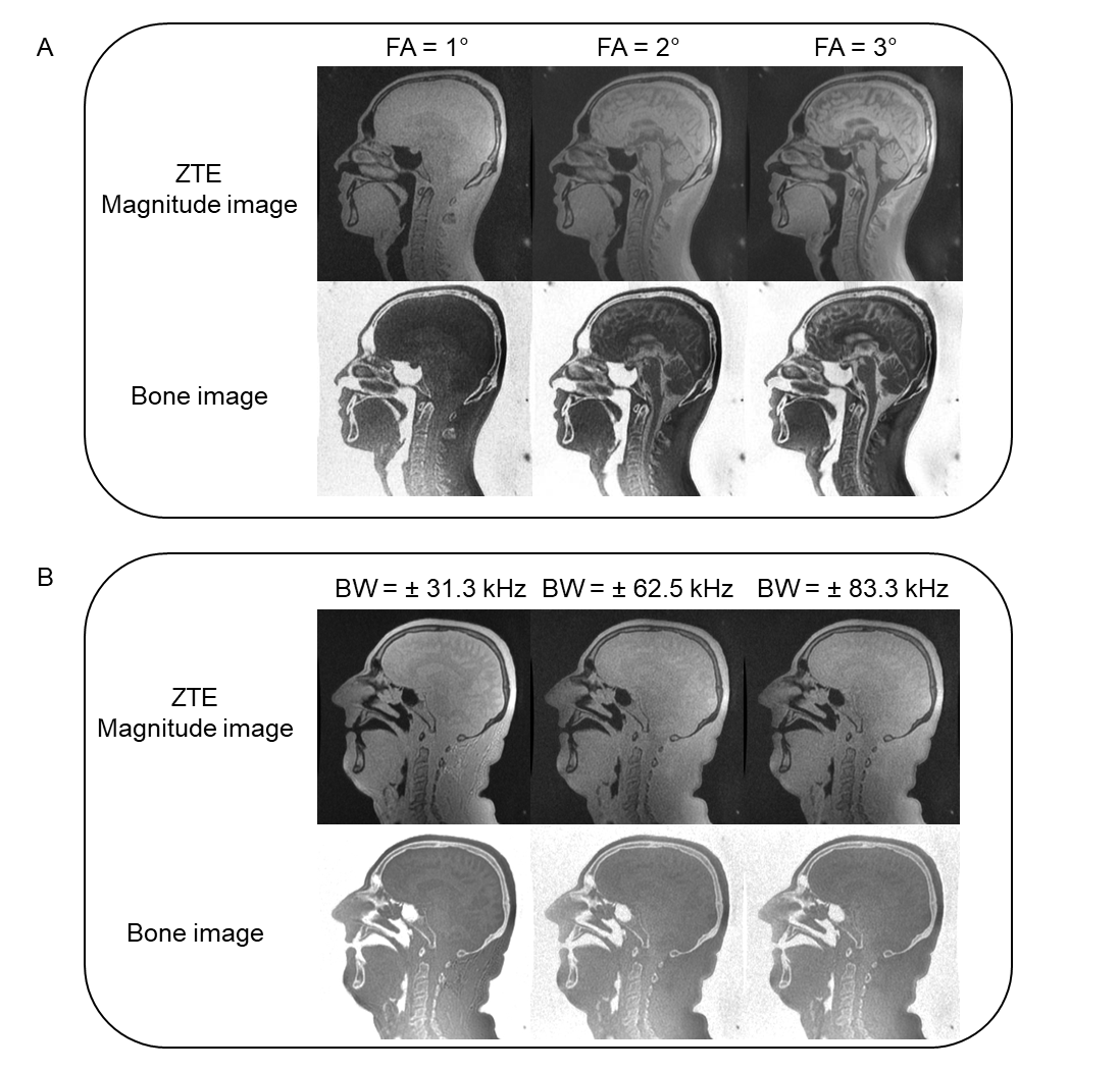
Volunteer: Four male volunteers (mean age 31.3 ± 10.1) were recruited for this study to optimize the ZTE sequence. Different flip angles (1°,2° and 3°) and RBWs (± 31.3, ± 62.5 and ± 83.3 kHz) were tested to achieve PD weighting and minimize off-resonance effects at tissue boundaries. The optimized parameters were used for the patient scan.
Patient: One male patient (age 78) with known calcification in conventional contrast weighted images was scanned using this protocol. The contrast weighted images included 3D T2*w using fast spoiled gradient echo and 2D TOF.
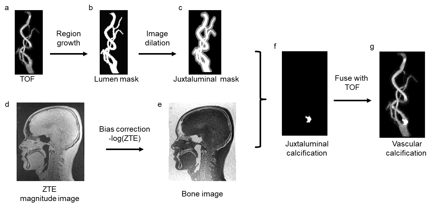
Image processing: The workflow of proposed vascular calcification imaging is shown in Figure 1. The TOF image was used to generate the juxtaluminal mask (Figure 1a-c). A histogram-based bias correction was applied to the ZTE images 3, before it was converted into the bone image by inverse-logarithmic operation (Figure 1d-e). The juxtaluminal mask was then applied to the bone image to get the calcification information only at juxtaluminal area (Figure 1f). The images were processed using Matlab (MATLAB 2016b, Mathworks, Natick, MA). The calculated images were then fused with TOF for CTA-like visual appearance (Figure 1g), using OrisiX (OsiriX 5.5.2, Pixmeo, Geneva, Switzerland). The generated images were then compared with other contrast weighed images at the same image location.
Results
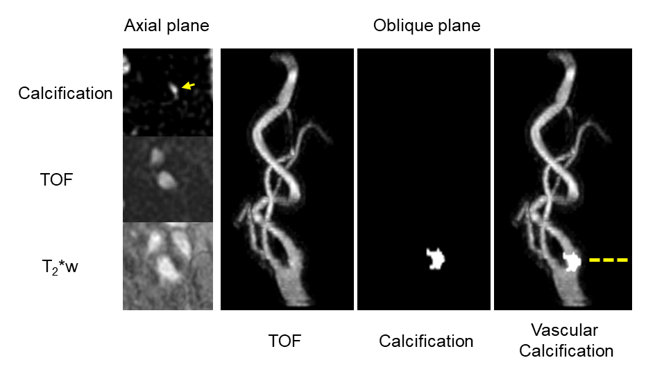
The volunteer images at different flip angles and RBWs are shown in Figure 2. A small flip angle (1°) achieved PD weighting while larger flip angles result in T1 saturation which confuses the bone appearance in the inverse image display. Smaller RBW images have severe off-resonance effects while large RBW eliminates these. Therefore, a small flip angle (1°) and large RBW (≥ ± 62.5 kHz) were used for the patient scan. In the patient scan, one vascular calcification was found using the proposed protocol. An example of the calcification image comparing with TOF and T2*w images is shown in Figure 3. Good correlation was found between the hyper-intense signal in calcification image with the hypo-intense signal in the T2*w and TOF images.Conclusion
The optimized ZTE sequence together with TOF sequence could be used for carotid vascular calcification imaging, with the scanning time of less than 10 mins. The protocol showed good sensitivity in detecting vascular calcification compared with traditional contrast weighted images.Acknowledgements
We acknowledge funding from NIHR BRC and Addenbrooke's Charitable Trust.References
1. Naghavi M, Libby P, Falk E, et al. From vulnerable plaque to vulnerable patient. Circulation. 2003;108(14):1664-72.
2. Saam T, Ferguson MS, Yarnykh VL, et al. Quantitative evaluation of carotid plaque composition by in vivo MRI. ATVB. 2005;25(1):234-9.
3. Wiesinger F, Sacolick LI, Menini A, et al. Zero TE MR bone imaging in the head. MRM. 2016;75(1):107-14.
4. Breighner R, Endo Y, Konin G, et al. Zero Echo Time MRI: Osseous Shoulder Imaging. ISMRM. 2017:0849.
Figures