3399
Improving arterial spin labelling at ultra-high field using parallel transmission: a simulation study1Wellcome Centre for Integrative Neuroimaging, FMRIB, Nuffield Department of Clinical Neurosciences, University of Oxford, Oxford, United Kingdom
Synopsis
Implementing ASL at ultra-high field is challenging due to increased B1+ and B0 inhomogeneity. Parallel transmission (pTx) provides additional degrees of freedom to mitigate B1+ inhomogeneity. Among various pTx strategies, RF shimming is a simple formulation that modulates the complex weights of each RF channel. RF shimming is particularly robust for applications involving small regions-of-interest. In this study, we explored the possibility of using RF shimming for ASL via simulation, and RF shimming is shown to achieve improved lower NRSME and improved labeling homogeneity over CP mode through simulation.
Introduction
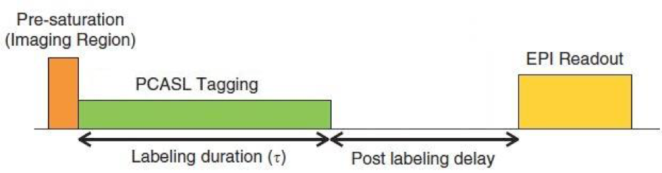
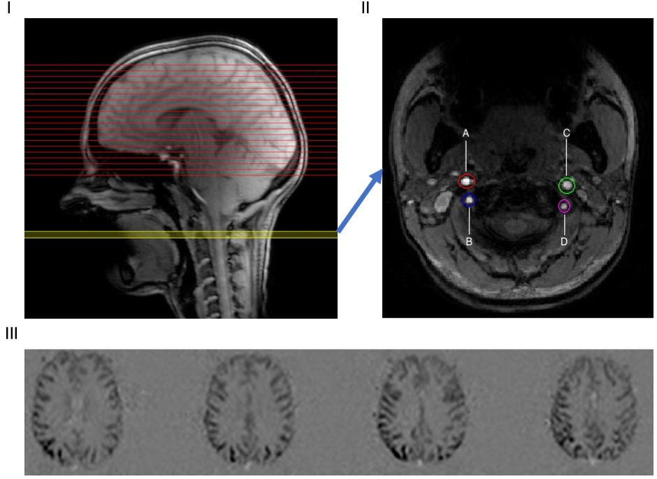
Arterial spin labeling (ASL) is a commonly used non-invasive perfusion imaging technique with various clinical applications such as acute stroke, dementia, and chronic vascular diseases.1 Yet its implementation at ultra-high field (>3 tesla) is not trivial.2 During an ASL scan, spins in blood vessels upstream of the imaging plane are inverted or saturated (labeled). After a post-labeling delay of 1-2 s, a proton-density weighted image is acquired usually with EPI readout (Fig 1).2 The blood is labelled in the four main brain-feeding arteries: the right internal carotid artery (RICA), right vertebral artery (RVA), left internal carotid artery (LICA), and left vertebral artery (LVA) (Fig 2).
An increase of B1+ and B0 inhomogeneity at higher field strength leads to poor labeling efficiency, which diminishes the perfusion signal.2 The specific absorption rate (SAR) scales quadratically with field strength, reducing permitted labeling pulse duration and amplitude. Parallel transmission (pTx) provides additional degrees of freedom that allows for constructive and destructive interference of different radio-frequency (RF) waveforms to mitigate B1+ inhomogeneity. RF shimming (or “static pTx”), aims to produce a homogenised and more accurate flip-angle within the region of interest (ROI) by adjusting the complex weights of each available RF channel. In this study, we present an RF shimming strategy for homogenous ASL labeling under explicit power constraints.
Methods
B1+ maps, B0 maps and localisers were acquired from a single subject (female, 65 kg, 24 yrs) on a Siemens (Erlangen, Germany) Magnetom 7T scanner. The scanner is equipped with an 8 channel pTx system, with a Nova Medical Inc. (Wilmington MA, USA) 8Tx32Rx head coil. B1+ maps were acquired using a 2D “STE first” phase-cycled DREAM sequence.3,4 B0 maps were acquired using a dual-echo gradient-echo sequence. A time-of-flight (TOF) sequence was used to identify the four arteries in the labeling plane. Four elliptic ROIs through 3 slices (thickness = 2.5 mm) were manually selected around the four arteries from the TOF image. (PC)ASL sequence simulation parameters: Hann-window labeling pulse, Tp = 600 μs, pulse interval = 1 ms, and labeling duration = 1.4 s.
The flip-angle optimisation strategy was based on an algorithm by Dupas et al.5 A spin dynamics matrix A was constructed, including off-resonance, transmit sensitivities, and each voxel’s position, and the gradient waveforms and RF pulse shape. The RF shimming problem is then presented as one that minimizes || |Ab| - θ||2, subject to explicit per channel and sum-of-channels average and absolute power limits where b is the complex weight of each RF channel in Volts, and θ is the desired flip-angle in each voxel in the ROI.6
The Active-Set (A-S) method was employed to solve the magnitude least square problem above in MATLAB (The MathWorks, Natick, MA, USA).7 The variable-exchange method, with an initial phase of that from the CP mode B1+ phase map, was used to initialize the problem.8 Different Tikhonov regularization constants “λ” were used to provide initial solutions with different power content (λ = 10-6, 10-5, 10-4, 10-3, 10-2, 10-1).
The same algorithm was extended to “phase-only” shimming (all channel amplitudes = 1). 20 random phase settings were used for initialisation. The final results of all optimisations were checked using full Bloch Equation simulation.9 Labeling efficiency of the two strategies were also calculated by simulating the magnetisation of a PCASL sequence using a Bloch Equation simulator.10 The results were compared with the results of an optimally scaled CP mode labeling pulse.
Results
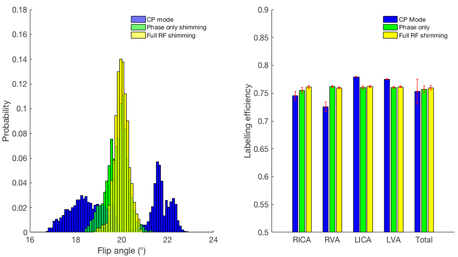
The TOF localiser (including ROI selection), a B1+ map and a B0 map are shown in Figure 3. The achieved shimmed flip-angle is shown for each optimised case. NRMSE of the labeling flip angle for full RF shimming, phase only shimming, and CP mode amplitude modulation are 1.55%, 2.59% and 8.68%, respectively. RF shimming achieves a better result than CP mode amplitude modulation, and a moderately better result than phase-only shimming. The distribution of flip-angles and labeling efficiency of each mode, in each labelled artery, are shown in Figure 4.Discussion
Unlike dynamic pTx, RF shimming does not involve calculation of a full RF waveform, nor optimisation of the gradient trajectory. Although it is challenging to achieve homogeneous B1 distribution over a large field-of-view, RF shimming provides excellent results in the small ROIs in this study with short calculation time.Conclusion
RF shimming was shown to be a robust method to improve labeling efficiency for ASL at ultra-high field. We look forward to extending this simulation study to in vivo experiments.Acknowledgements
This study was supported by China Oxford Scholarship Fund, Dunhill Medical Trust, and the NIHR Oxford Health Biomedical Research Centre. The Wellcome Centre for Integrative Neuroimaging is supported by core funding from the Wellcome Trust (203139/Z/16/Z).References
1. Okell, T.W., et al., Cerebral blood flow quantification using vessel-encoded arterial spin labeling. J Cereb Blood Flow Metab, 2013. 33(11): p. 1716-24.
2. Teeuwisse, W.M., A.G. Webb, and M.J. van Osch, Arterial spin labeling at ultra‐high field: All that glitters is not gold. International Journal of Imaging Systems and Technology, 2010. 20(1): p. 62-70.
3. Tse, D.H., et al., Encoding methods for B1(+) mapping in parallel transmit systems at ultra high field. J Magn Reson, 2014. 245: p. 125-32.
4. Nehrke, K. and P. Bornert, DREAM--a novel approach for robust, ultrafast, multislice B(1) mapping. Magn Reson Med, 2012. 68(5): p. 1517-26.
5. Dupas, L., et al., Two-spoke placement optimization under explicit specific absorption rate and power constraints in parallel transmission at ultra-high field. Journal of Magnetic Resonance, 2015. 255: p. 59-67.
6. IEC 60601-2-33:2010 Medical electrical equipment - Part 2-33: Particular requirements for the basic safety and essential performance of magnetic resonance equipment for medical diagnosis. 2010.
7. Constrained Nonlinear Optimization Algorithms. MATLAB & Simulink - MathWorks. https://uk.mathworks.com/help/optim/ug/constrained-nonlinear-optimization-algorithms.html - brnox01. Accessed November 8, 2001
8. Hoyos-Idrobo, A., et al., On variant strategies to solve the magnitude least squares optimization problem in parallel transmission pulse design and under strict SAR and power constraints. IEEE Trans Med Imaging, 2014. 33(3): p. 739-48.
9. Bloch, F., Nuclear Induction. Physical Review, 1946. 70(7-8): p. 460-474.
10. Dai, W., et al., Continuous flow-driven inversion for arterial spin labeling using pulsed radio frequency and gradient fields. Magn Reson Med, 2008. 60(6): p. 1488-97.
Figures
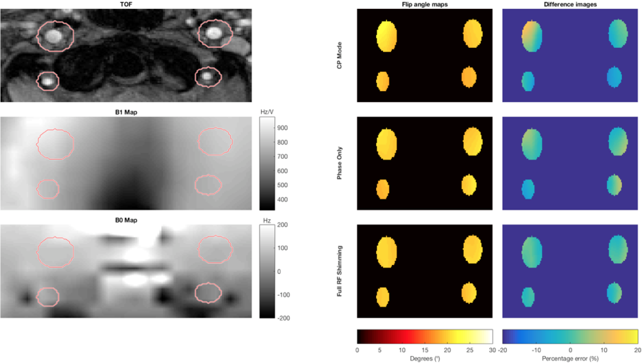
Left: Time-of-flight image, γB1+ map in Hz/V and B0 map in Hz with reduced field-of-view of the labeling plane. The four main blood-feeding arteries were manually selected as a ROI. Right: Flip angle maps and percentage error images of three optimisation strategies of labeling homogeneity: optimised CP mode, phase-only and full RF shimming (phase and amplitude).