3396
k-Space Domain Parallel Transmit Pulse Design1Biomedical Engineering, Vanderbilt University, Nashville, TN, United States
Synopsis
Current parallel transmit pulse design methods are based on a spatial domain formulation that has prohibitive memory and computational requirements when the number of coils or the number of dimensions is large. We describe a k-space domain parallel transmit pulse design method that directly solves for the columns of a sparse design matrix with a much smaller memory footprint than existing methods, and is highly parallelizable. The method is validated with phantom and in vivo 7T 8-channel spiral excitations.
Introduction
Parallel transmission enables the excitation of multidimensional selective patterns with short RF pulse durations [1,2], and has been applied to enable reduced-FOV imaging and mitigation of B1+ inhomogeneity. The spatial-domain formulation is currently the most widely used approach for parallel transmit pulse design [3], but for large problem sizes (as in high-resolution 2D pulse design, many-coil parallel excitation, 3D and spectral-spatial pulse design), matrix inverse and iterative solutions have large memory and/or computational requirements. Here we introduce and validate a k-space-based approach to parallel transmit pulse design that has low memory and computational requirements, and is highly parallelizable.Methods
The k-space domain pulse design method solves for the columns of a sparse matrix $$$\mathbf{W}$$$ that relates the discrete Fourier transform of a target pattern $$$\mathbf{d}$$$ to a vector of RF pulses, as:
$$\hat{\mathbf{b}} = \mathbf{W}\mathcal{F}\left(\mathbf{d}\right)$$
where the designed pulses are stacked end-on-end in the vector $$$\hat{\mathbf{b}}$$$. Each column of $$$\mathbf{W}$$$ represents a location in the target excitation k-space grid, and contains a set of weights that relate the desired energy at that target location to the RF pulses. These weights can be determined column-by-column, by solving the system of equations that results from discretizing the following equation over the neighborhood around each target location:
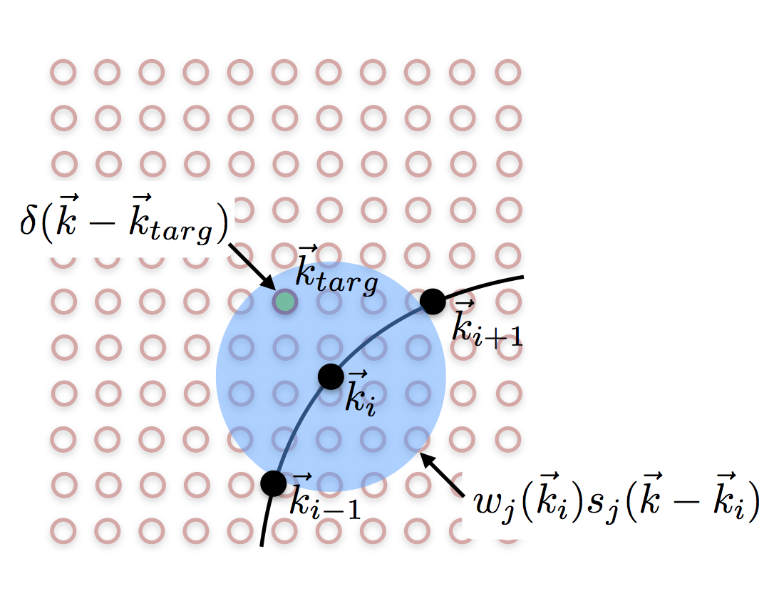
$$\delta(\vec{k}-\vec{k}_{targ}) = \sum_{i \in traj} \sum_{j \in coils} w_j(\vec{k}_i) s_j(\vec{k}-\vec{k}_i)$$
where $$$i$$$ indexes excitation trajectory locations $$$\vec{k}_i$$$ that are near the target location $$$\vec{k}_{targ}$$$. Figure 1 illustrates this equation graphically. The discretized system of equations can be recast in matrix-vector form, as:
$$\mathbf{Sw} = \mathbf{\delta}$$
where $$$\mathbf{\delta}$$$ is a vector that contains a one at the target location, and zeros elsewhere. The weights vector can be solved using regularized pseudoinverse, as:
$$\hat{\mathbf{w}} = \left(\mathbf{S}^H\mathbf{S} + \lambda \mathbf{I}\right)^{-1} \mathbf{s_{targ}}^{H}$$
where $$$\mathbf{s_{targ}}= \mathbf{S}^H\mathbf{\delta}$$$ is the row of the matrix $$$\mathbf{S}$$$ corresponding to the target location. The weights are then inserted into the sparse matrix $$$\mathbf{W}$$$ for pulse design.
Experiments were performed to validate the k-space domain pulses and compare them to spatial domain pulses designed using a regularized matrix pseudoinverse. First, B1+ maps were measured in a 3D-printed head phantom on a 7T scanner (Philips Healthcare, Best, Netherlands) with 8-channel parallel transmit. B1+ map processing, B0 shimming, and RF pulse interfacing was performed with MRCodeTool (MRCode BV, Zaltbommel, Netherlands). Spiral-in RF pulses were designed to excite an oval region in the middle of the brain phantom with 7.5 cm excitation-FOV, 0.7 cm resolution, 3.4 ms duration, and one-degree flip angle. The same pulse design was repeated for a healthy human volunteer with IRB approval, but was scaled to 90 degrees and used as a saturation pulse, followed by a crusher and a one-degree excitation. In both cases the excitation patterns were imaged with a gradient-recalled echo sequence with TE/TR = 2/100 ms. The k-space domain designs used 20 x 20 neighborhoods around each target location.
Results
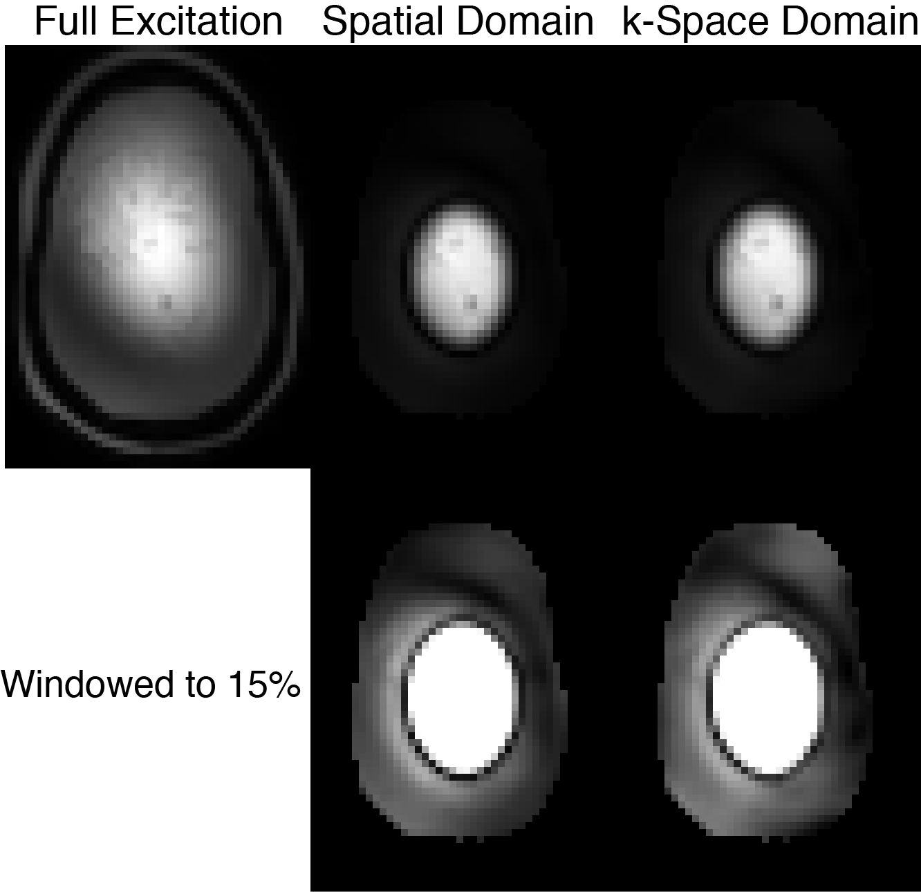
Figure 2 shows full-scale and windowed-down phantom excitation pattern images. The spatial domain-designed pulses had lower design error than the k-space domain pulses (1.7% versus 6.1% NRMSE with the same RMS RF amplitude), but the imaged patterns contain no significant differences. Figure 3 shows in vivo images with midbrain saturation. The spatial domain-designed pulses again had lower design error (2.9% versus 7.4% with the same RMS RF amplitude), but the shape and quality of the saturation regions are indistinguishable. The number of nonzero elements in the k-space domain designs' W matrices was 350,000, while the number of elements in the inverse spatial domain matrix was 14.5 million.Discussion
The presented k-space domain method is related to the method of Katscher et al [1], but that method does not decouple calculation of the design matrix columns, or take advantage of the limited support of B1+ maps in the frequency domain. As a result, it has the same computational and memory requirements as the spatial domain method [3]. Errors in k-space domain pulse designs will predominantly appear at the boundaries of the excited volume, where the B1+ maps will be rounded off due to k-space truncation. This may be mitigated by growing the maps past the boundary or using other means to restrict their frequency content. Our next steps will be to parallelize the weight computations across target locations/columns of W, extend the design to 3D and spectral-spatial pulse designs, and implement off-resonance-compensated k-space pulse design using time- or frequency-segmentation.Conclusion
A new k-space domain parallel transmit pulse design method was described, which has reduced memory requirements compared to existing spatial domain formulations (41x smaller for the presented spiral designs), and can be finely parallelized.Acknowledgements
This work was supported by NIH grants R01 EB 016695 and U01 EB 025162.References
- U. Katscher, P. Boernert, C. Leussler, and J. S. van den Brink. Transmit SENSE. Magn Reson Med, 49(1):144–150, Jan 2003.
- Y. Zhu. Parallel excitation with an array of transmit coils. Magn Reson Med, 51(4):775–784, Apr 2004.
- W. A. Grissom, C. Y. Yip, Z. Zhang, V. A. Stenger, J. A. Fessler, and D. C. Noll. Spatial domain method for the design of RF pulses in multicoil parallel excitation. Magn Reson Med, 56(3):620–9, Sep 2006.
Figures