3249
Brain extraction and segmentation framework for bias field rich cranial MRI scans of rats1Department of Computer Science, University of Copenhagen, Copenhagen, Denmark, 2Center for Translational Neuromedicine, University of Copenhagen, Copenhagen, Denmark, 3Anesthesiology, Yale School of Medicine, Yale University, New Haven, CT, United States, 4Center for Translational Neuromedicine, University of Rochester, Rochester, NY, United States
Synopsis
This abstract presents a framework to extract brain tissue and internal Cerebrospinal fluid in cranial magnetic resonance imaging of rats with strong bias fields. Desired segments are obtained through bias field correction and several passes of segmentation. A refinement procedure is proposed to remove brain surface CSF. Promising planar and 3D visualizations of results are presented and demonstrate the capabilities of the framework.
Introduction
Magnetic resonance imaging employing surface receive coils often faces the problem of strong image bias fields in data that makes relevant tissue extractions very challenging, as bias field correction algorithms cannot fully correct for it. We present a framework for the extraction of rat brain tissue and the cerebrospinal fluid (CSF) networks, in the case where MR volumes are affected by strong bias fields. We demonstrate that our framework obtains very satisfactory segmentation results.
Animals
Unaffected male rats of the Wistar Kyoto stain (WKY) and spontaneously hypertensive rats (SHR) were obtained from Charles River, Germany. Separate groups of rats were scanned at two age-ranges: young (7-9 weeks old; WKY7, n = 11; and SHR7, n = 8) and young adults (19-21 weeks WKY19, n = 8; and SHR19, n = 9). All treatments and imaging were performed according to protocols approved by the IACUC, and according to a protocol approved by the University of Copenhagen animal experimentation committee.
MRI
All MRI investigations was conducted on a 9.4 T magnet (Bruker Biospec 9.4/30 USR) interfaced to a Bruker Advance III console and controlled by Paravision 5.1 software (Bruker BioSpin) at the Panum Institute, University of Copenhagen. Imaging was performed with an 86 mm3 volume resonator and a surface quadrature array receiver coil. Images were acquired with the spoiled gradient FLASH3D sequence (TE: 4 ms, TR: 15 ms, NA: 3; matrix: 128 x 128 x 128, voxel size: 0.24 x 0.24 x 0.26 mm, FA: 15°, scan time: 4:05 min).
Methods
The proposed framework consists of 4 major steps and is illustrated in Figure 1. Each step is explained below.
Bias field correction: A standard bias field correction method[] is applied. This alone does not completely remove the bias and standard segmentation methods fail to deal with it.
2-class segmentation: The local-means method proposed in [2, 3] is used and seeks to minimize the functional
$$\mathcal{E}_Q(\mathbf{c},\mathbf{v})=\frac{1}{2}\sum_{i=1}^{n}\int_{\Omega}g*\left[u-c_i(\mathbf{x}))^2\mathbf{v}_i\right]d\mathbf{x}+\frac{\mu}{2}\sum_{i=1}^{n}\int_{\Omega}|D\mathbf{v}_i|^2$$
where $$$\mathbf{v}_i\in[0,1]$$$ is the label field describing the probability of belonging to class i. $$$u$$$ is the bias corrected volume, $$$g$$$ a moving average kernel and
$$c_i(\mathbf{x})=\frac{(u\mathbf{v}_i)*g(\mathbf{x})}{\mathbf{v}_i*g(\mathbf{x})}$$
This method produces a clear contour of the brain tissue, with strong edges, that makes rough brain extractions possible.
GAC brain extraction: A full brain mask is retrieved from the skull, by initializing a Geodesic Active Contour (GAC) based model[4, 5] in the center of the segmented brain. Any ’holes’ that would occur in the resulting brain mask are filled, using mathematical morphology operations.
3-class segmentation: The retrieved brain mask is used to extract the brain tissue segment of the binary segmentation result and is in turn segmented by a tighter 3-class local-means segmentation. The three classes are background, CSF, and brain tissue. A single connected brain tissue component is expected, so only the largest is kept.
To refine the segmentation of the internal CSF network, we process as follows. A run of the GAC method on the final brain tissue class provides a more accurate brain mask. It is used to extract the internal CSF network from the final CSF class, removing surface CSF. Small objects are removed in the CSF class to highlight larger networks in the brain.
Results
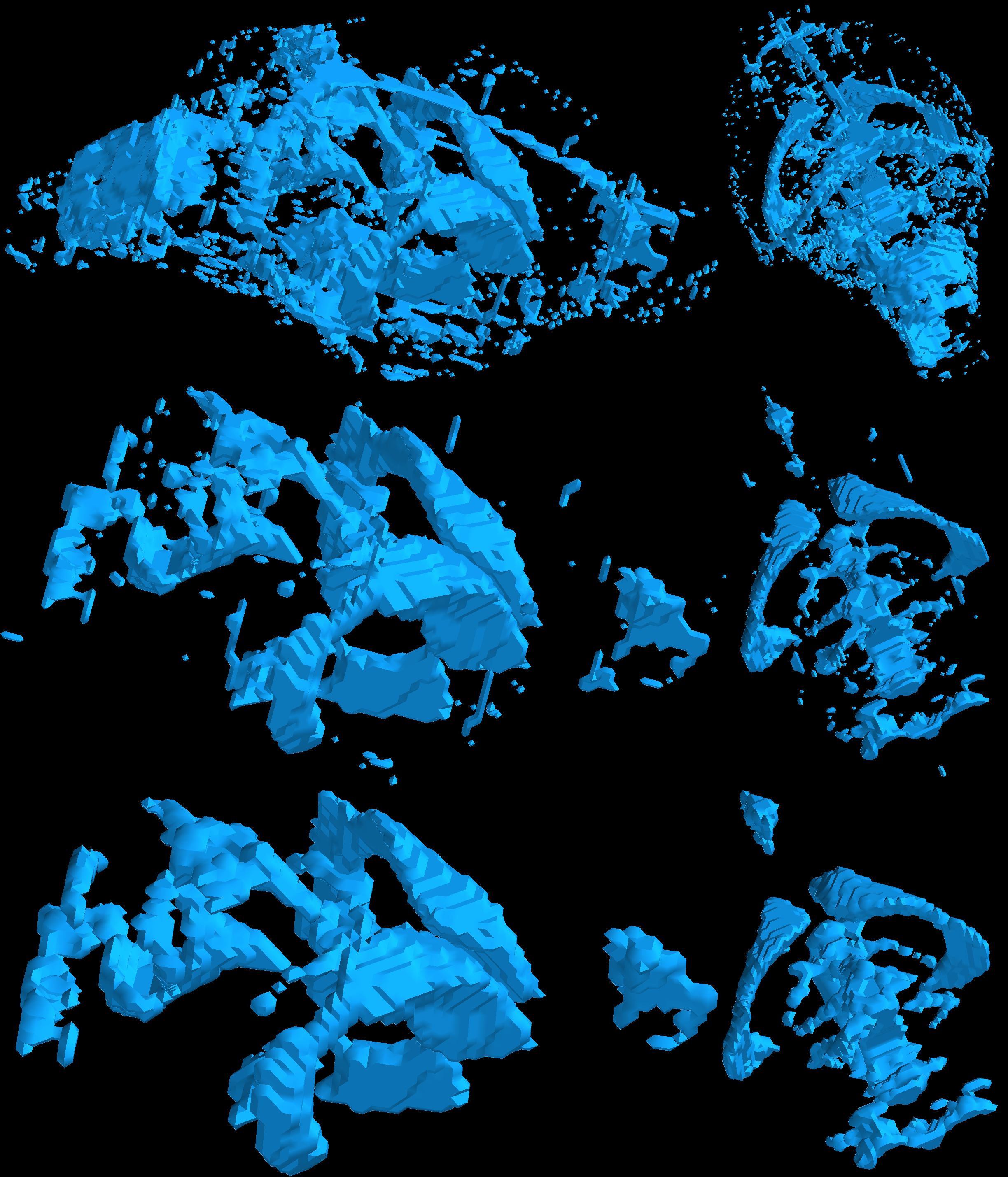
The framework is run on a sample rat cranium volume affected by significant bias. In Figure 2 the result of step 2 and 4 are shown for different brain slices.
Figure 3 presents a 3D surface view of the combined brain tissue matter (pink) and CSF (blue) for different viewing angles. In Figure 4 and 5 respectively, the 3D surfaces of the isolated brain tissue and CSF network can be seen.
Discussion and conclusion
A framework that satisfactorily segments and extracts brain tissue and internal CSF networks in rat brain MRI scans affected by strong image bias fields has been proposed. The framework combines bias field correction with several passes of segmentation to adequately extract the relevant classes. 3D surface results for brain tissue and the major CSF network as well as axial, sagittal, and coronal planes have been presented.
To further improve on the results, a distance based feature could be incorporated, as the severity of the bias field is correlated with the distance to the coils. Additionally, strong priors on the connectivity of the CSF network will be integrated in the model. While the framework introduces more parameters, we believe the improvements in extracting high quality tissues from medical imaging affected by strong bias fields are highly beneficial.
Acknowledgements
No acknowledgement found.References
[1] Tustison, N.J., Avants, B.B., Cook, P.A., Zheng, Y., Egan, A., Yushkevich, P.A. and Gee, J.C. N4ITK: improved N3 bias correction. in IEEE transactions on medical imaging (2010), pp.1310-1320.
[2] Hansen, J. D. K., and Lauze, F. Local Mean Multiphase Segmentation with HMMF Models. In International Conference on Scale Space and Variational Methods in Computer Vision (2017), Springer, pp. 396–407.
[3] Brox, T., and Cremers, D. On Local Regions Models and a Statistical Interpretation of the Piecewise Smooth Mumford-Shah Functional. Int’l J. Computer Vision 84 (2009), 184–193.
[4] Álvarez, L., Baumela, L., Henríquez, P., and Márquez-Neila, P. Morphological snakes. In Computer Vision and Pattern Recognition (CVPR), 2010 IEEE Conference on (2010), IEEE, pp. 2197–2202.
[5] Márquez-Neila, P., Baumela, L., and Alvarez, L. A morphological approach to curvature-based evolution of curves and surfaces. IEEE Trans-actions on Pattern Analysis and Machine Intelligence 36, 1 (2014), 2–17.
Figures
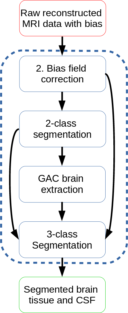
The proposed framework, highlighting each step as a box inside the dotted blue box. Arrows indicate that the output of the origin box is used as input in the destination box.

The rows highlight: The original image, showing a severe bias field; the bias field corrected image, which still has quite a bit of bias left; The final segmentation and extraction of the example MRI using the proposed framework. Each column provides the axial, sagittal, and coronal planes for the same brain. Brain tissue is light gray while CSF is is dark gray.
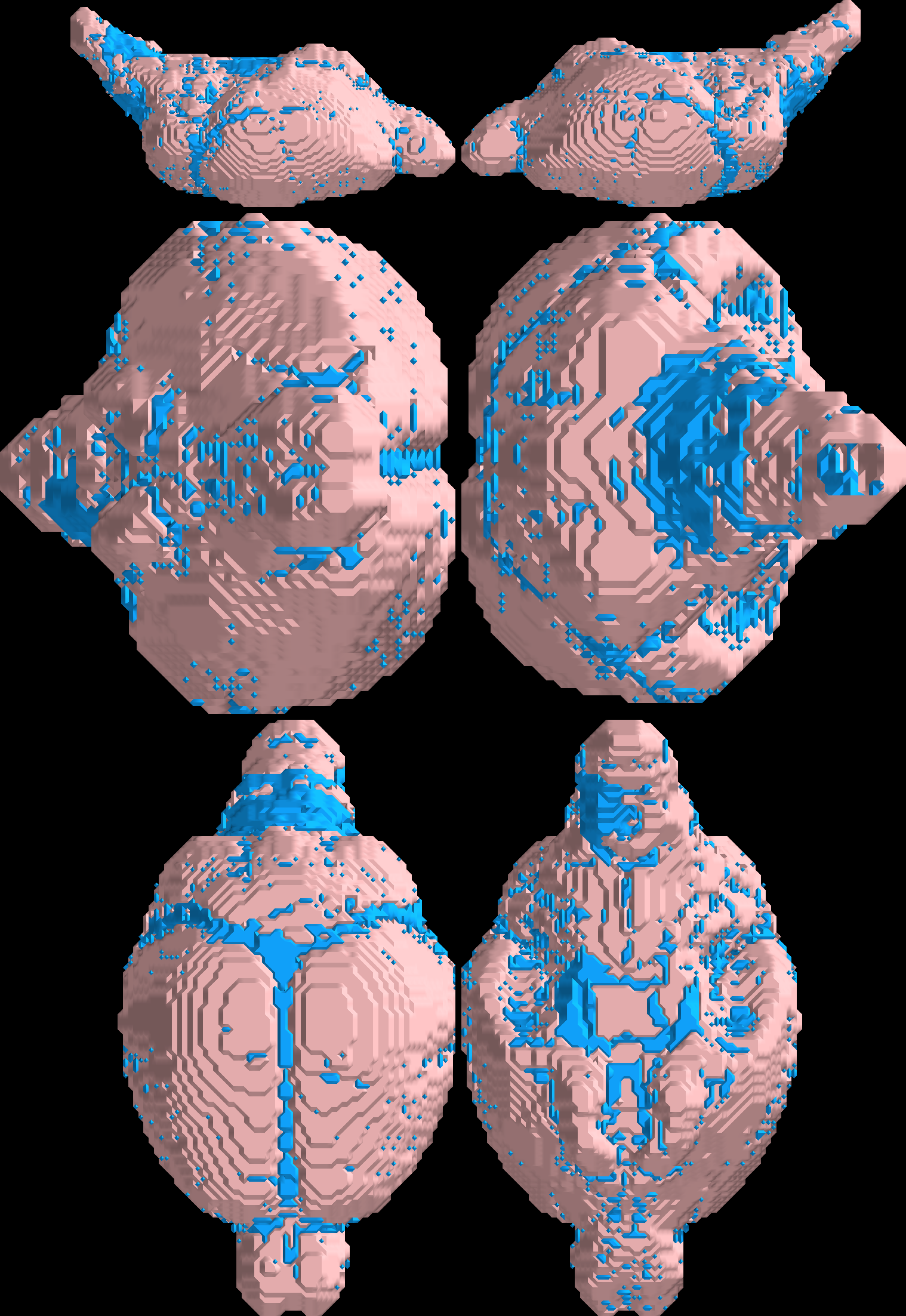
The columns show different viewing angles of the brain by rotating 180 degrees around the corresponding axis of the resulting brain. The rows from top to bottom show the x, y, and z direction for the same brain segmentation. Brain tissue is pink, while CSF is light blue.
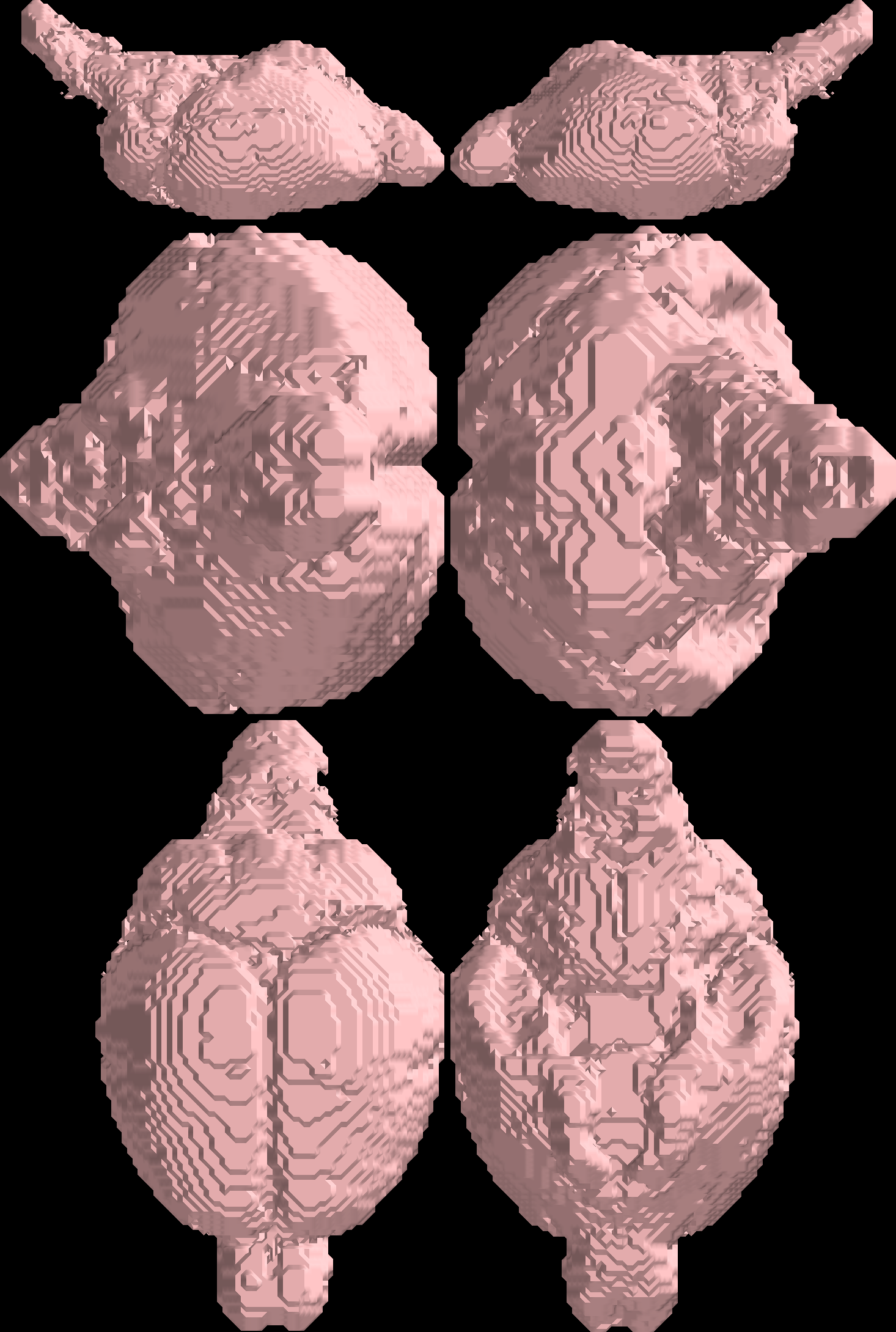
The columns from left to right show the negative and positive direction of the brain tissue (pink) segmentation, resulting from step 4. The rows from top to bottom show the x, y, and z direction for the same brain segmentation.