3225
Design of multi-purpose and 3D-printed fibre phantoms for investigating complex tissue microstructures1Institute of Biomedical Engineering and Nanomedicine, National Health Research Institutes, Miaoli, Taiwan, 2Institute of Neuroscience and Medicine – 4, Forschungszentrum Juelich, Juelich, Germany, 3Department of Neurology, Faculty of Medicine, RWTH Aachen University, Aachen, Germany
Synopsis
Investigating complex tissue microstructures has become of great interest during the past decade. One of the most promising MRI methods to map tissue microstructures is diffusion MRI. However, the validation of its accuracy in mapping fibre orientation and microstructural characteristics is still challenging. In this work, we have successfully designed and prototyped a fibre phantom using 3D printing and micro-scale fused silica capillaries. Our results show that susceptibility of the capillaries and/or the coating material is different from that of distilled water and suggest that our phantom design could provide detectable microstructures for further studies.
PURPOSE
METHODS
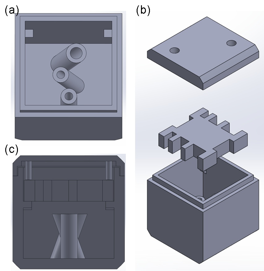
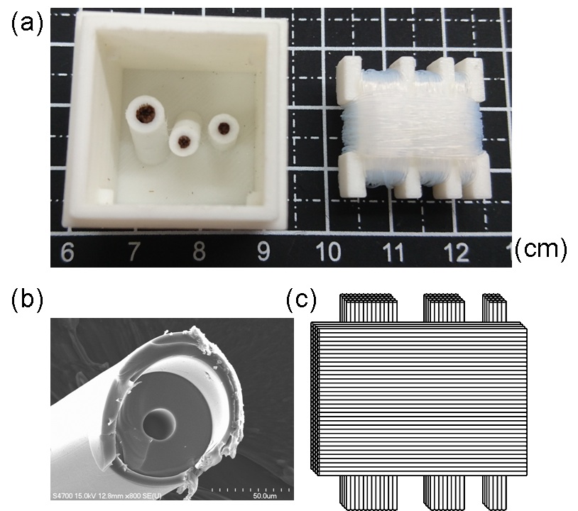
The supporting platform for the phantoms were designed and prototyped with polylactide (PLA) materials by a 3D printer (Kingssel 3070+, MASTECH MACHINE CO., LTD., Taiwan) as shown in Fig. 1. In our first phantom (bottom part), three tubes were designed to allow unidirectional fibre bundles to be placed along different angles (Fig. 1a). The capillaries with inner/outer diameters of 20/90 µm1 were used. After being filled with water using syringe pump, the capillaries were cut to 10 mm in length and then those were tightly inserted into the tubes to make unidirectional fibre bundles (Fig. 2a). Our second phantom consists of a 90o fibre-crossing structure built by winding bendable capillaries (inner/outer diameters of 50/350 µm)2 on a 3D-printed plate with several notches after filling the capillaries with water. Scanning electron microscopy (SEM) was used to evaluate whether the cutting process damages the microstructures of capillaries (Fig. 2b). All printed parts were fixed inside a cubic shell of side length of 26.5 mm and the phantom was filled with distilled water.
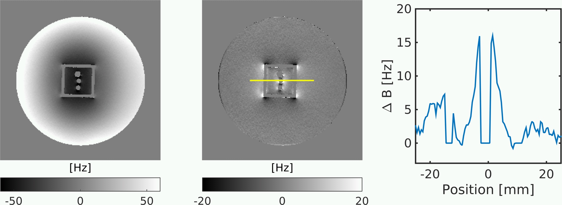
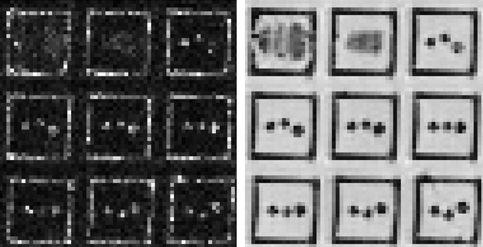
MR experiments were conducted on a 3T commercial MRI system using a 12-channel head coil (Trio, Siemens Healthineers, Erlangen, Germany). The designed phantom was positioned in a water bottle and immersed into water to evaluate field distortion induced by cubic shell and determine the magnetic susceptibility of the printing material. DTI data was acquired using a pulsed-gradient spin-echo 2D echo planar imaging sequence with TR/TE of 3000/81 ms, 1.5 mm isotropic voxel size, b-value of 1000 s/mm2, 12 noncollinear diffusion gradient directions and 32 averages. A field map was derived by recording a standard multi-echo gradient echo sequence with TR of 60 ms, TE of 2, 6, 10, 14, 18, 22 ms, bandwidth of 500 Hz/Pixel, matrix size of 256×256×160 and an isotropic resolution of 0.5 mm, unwrapping in time domain and least-squares linear regression fitting. Residual background fields from external sources were removed with MUBAFIRE3.
RESULTS
DISCUSSION AND CONCLUSIONS
We have successfully designed and prototyped the fibre phantoms using 3D printing and micro-scale capillaries. Both SEM and MRI results demonstrated that the microstructural characteristics in our designed phantoms are well manufactured and detectable even with low spatial resolution. Our preliminary findings also raise the following issues that we will address in future works. Firstly, in order to clearly associate the observed field distortion with their source, further measurements and simulation have to be performed. It is important to know the susceptibility of the capillaries in order to determine the affect of self-induced background gradients that could bias the results4. Second, some fibre phantoms were built using polyester textile for the validation or measurement of diffusion MRI techniques5,6. These phantoms can only provide “extracellular” diffusion, which is highly dependent on the packing density of fibre bundles. With the existence of “intracellular” or intra-tubular diffusion, capillary phantoms can provide more consistent diffusion anisotropy than textile fibre phantoms, and would be suitable for multiple purposes, such as quality assurance and multi-site harmonization. Advanced diffusion MRI techniques beyond DTI and other tissue microstructural modeling approaches will be investigated in the future on the fibre-crossing regions to extend its usability in further studies.Acknowledgements
This study is supported by NHRI intramural grants (NHRI-BN-PP-06, NHRI-BN-SP-01 and NHRI-BN-SP-05) and MOST-DAAD grant 106-2911-I-400-502.References
1. K.-H. Cho, C.-H. Yeh, et al. (2008). “Evaluation of the accuracy and angular resolution of q-ball imaging.” Neuroimage 42(1): 262-71.
2. C.-P. Lin, et al. (2003). “Validation of diffusion spectrum magnetic resoance imaging with manganese-enhanced rat optic tracts and ex vivo phantoms.” Neuroimage 19(3): 482-495
3. Lindemeyer J, et al. (2015) “Multistage Background Field Removal (MUBAFIRE)—Compensating for B0 Distortions at Ultra-High Field.” PLoS ONE 10(9): e0138325. https://doi.org/10.1371/journal.pone.0138325
4. Farrher E, Lindemeyer J, Grinberg F, et al. “Concerning the matching of magnetic susceptibility differences for the compensation of background gradients in anisotropic diffusion fibre phantoms.” PLoS ONE 12(5): e0176192. https://doi.org/10.1371/journal.pone.0176192
5. Poupon, C., et al. (2008), New diffusion phantoms dedicated to the study and validation of high-angular-resolution diffusion imaging (HARDI) models. Magn. Reson. Med., 60: 1276–1283.
6. Watanabe, M., Aoki, S., Masutani, Y. et al. “Flexible ex vivo phantoms for validation of diffusion tensor tractography on a clinical scanner” Radiat Med (2006) 24: 605
Figures