3017
Integrated, 3D Printed Cost Effective Phantom solution for MR Imaging of Cardiac Structure and Function1Medical Imaging Research Centre, Dayananda Sagar Institutions, Bangalore, India, 2Healthcare, Wipro-GE, bangalore, India, 3Department of Radiology, Columbia University Medical Centre, New Y0rk, NY, United States
Synopsis
An integrated cardiac phantom solution was developed to correlate with clinically relevant parameters entered through a user interface (UI). Mimicking of human heart was achieved through integration of a flexible 3D printed heart model and peristaltic pump. Results depict the correlation between the input parameters to output parameters obtained through image processing of the phantom MR images. The work illustrates the structural features and motion measures of the cardiac phantom. The phantom can therefore be employed to assess novel acquisition and reconstruction methods. The utilization of 3D printing enables the use of subject specific phantom to study diverse cardiovascular scenarios.
Purpose/Introduction
In vitro cardiac phantoms play a critical role in the assessment of newly developed pulse sequence and reconstruction techniques1, in addition to understanding of the pathophysiology2. The goal of this work was to develop an integrated, cost effective cardiac phantom solution that correlates user provided parameters with measures from the resulting MR images. The utilization of 3D printing allows subject specific phantom models to study diverse cardiovascular scenarios. The details of the 3D printing have been reported previously3. In comparison, the phantom and the solution described here are hollow and integrated with post-processing of MR images depicting quantification of motion extent and correlation to clinical parameters such as beats per minute and flow rate.Methods
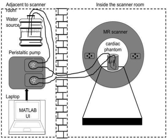
Phantom solution: The phantom was printed using Ninjaflex material (J Group Robotics) .The support material was removed carefully to provide anatomically accurate details for imaging. The phantom was covered with a layer of water resistant glue to ensure that there was no leakage. The peristaltic pump was customized with two motors that caused the motion in the phantom. The pump was interfaced to a laptop through a RS232 cable to vary the input parameters. The software model of the heart4 and the resulting 3D printed heart are shown in figure 1(a, b). The table shown in figure 1c details the components utilized for the assembly of the phantom solution along with associated costs and sources. The UI designed in MATLAB (The Mathworks Inc., MA) allowed inputs of Beats Per Minute (BPM) and flow rate. The input parameters were converted to flow rates and fed to the pumps by employing equations (1,2) as in ref3 . Two pipes were used for pumping water into the phantom from the water source. The pipes were inserted into the printed phantom till the ventricles to ensure the effective forward and reverse flow of water with respect to the pump. The printed heart model is housed in the cylindrical container. The setup of the phantom for imaging is as depicted in the figure 2. Acquisition: Five cardiac phantom MR datasets were acquired with different combinations of BPM and flow rates on a GE 1.5T MR450W scanner. BPM was varied between 40-60 in steps of 10 and flow rate of 3500-4500 ml/min varied in steps of 500. The acquisition parameters for the structural scan of the phantom were TE/TR=10/540ms, slice thickness with 4mm. Fast Imaging Employing Steady State Aquisition based cardiac cine sequence with TE/TR= 3.22/6.9ms, 8 slices with slice thickness of 4.3mm was acquired. Image processing: The Region of Interests (ROIs) were drawn to measure the perimeter of the inner wall diameter of the phantom. ROI was drawn utilizing ImageJ software5 for all the datasets. The perimeter for each of the ROI was tabulated and compared across different frames of the acquisition. This was performed on data sets with varying BPM and flow rates to evaluate the affect of these parameters on the difference in perimeters of the ROI due to motion.Results
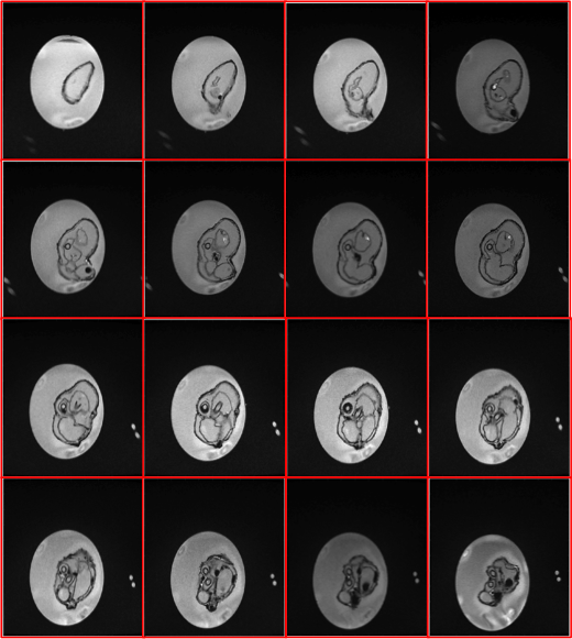
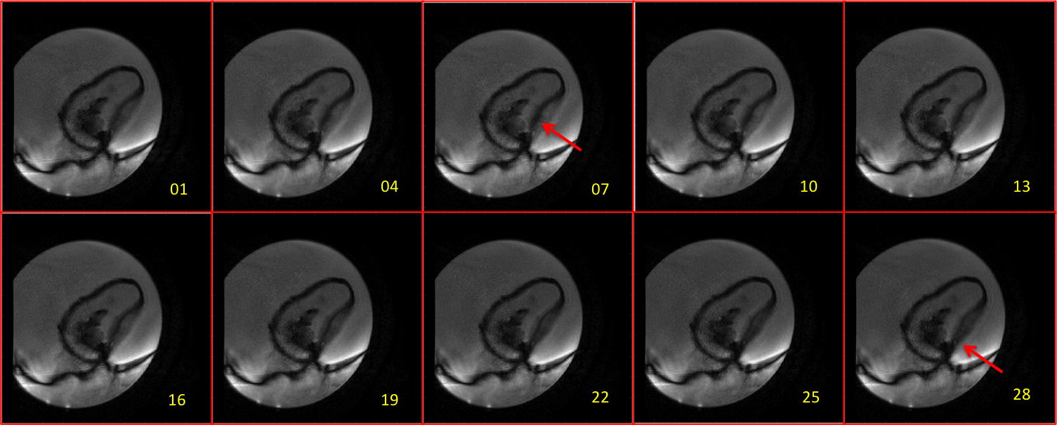
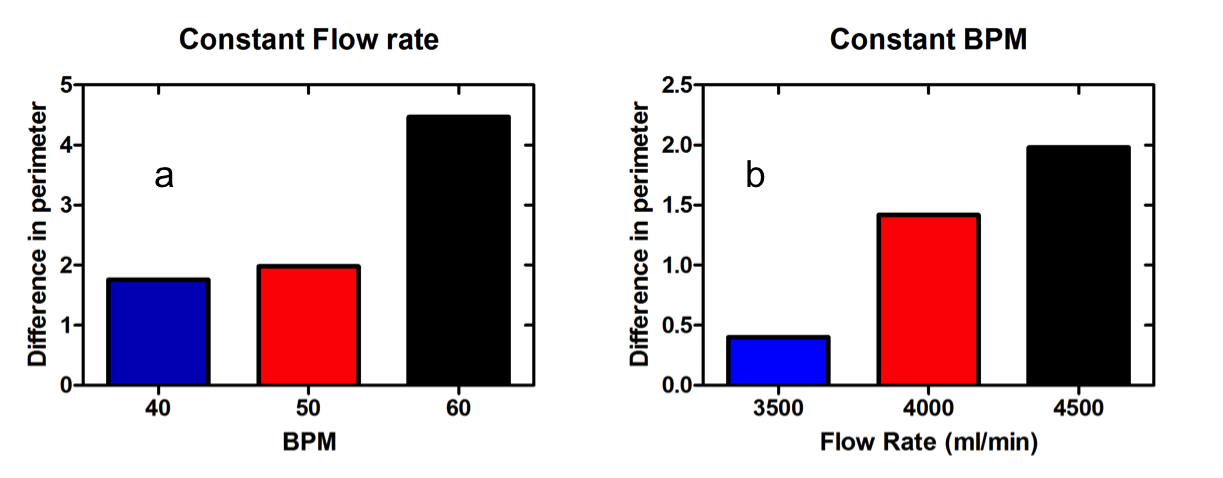
The anatomical details of the printed phantom are shown in figure 3 from apex of the heart towards aortic region. Variation in the contrast of the water in container is due to the sensitivity of the coil used for imaging. The representative data to demonstrate the motion of the wall is as depicted in figure 4. The red arrows in the figure 4 points at the corresponding region of maximum motion. The results show increase in the perimeter of the ROI and also the extent of motion for a maximum flow rate of 4500 ml/min and varying the BPM in UI. There is a decrease in the perimeter for constant BPM of 50 and a decrease in flow rate from 4500-3500ml/min in steps of 500 ml/min. The results show there is a correlation between the input parameters in UI to those of the parameters obtained after processing of images.Discussion and Conclusion
The cardiac phantom is controlled through a User Interface (UI) with clinical parameters as input3. Beats per minute and flow rate are considered as the two parameters for the study. Parameters were extracted through image processing techniques to find the correlation between the input parameters to that of parameters obtained through image processing. The maximum extent of motion measured was in case of the 60 BPM and maximum flow rate of 4500 ml/min as expected. Imperfections on the surface of the printed cardiac phantom due to the limitation of the available models and printing resolution, may prohibit the study of CMR angiography.Acknowledgements
1. This work was supported by Vision Group on Science and Technology (VGST), Govt. of Karnataka, Karnataka Fund for strengthening infrastructure(KFIST), GRD#333/2015
2. Department of Science and Technology (DST), Govt. of India under the program Technology Systems Development (TSD) for the project “Novel acquisition and reconstruction strategies to accelerate magnetic resonance imaging using compressed sensing”, No: DST/TSG/NTS/2013/100-G.
3. Department of Information Technology (DIT), Govt. of India for the project "Indigenous - Magnetic Resonance Imaging (I-MRI)- A national Mission"
References
1. Keenan, Katy, et al. "Standardized phantoms for quantitative cardiac MRI." Journal of Cardiovascular Magnetic Resonance 17.1 (2015): W36.
2. Ersoy, M., et al. "A left ventricular motion phantom for cardiac MRI." Proc. Intl. Soc. Mag. Reson. Med. Vol. 19. 2011.
3. Shivaprasad Ashok Chikop et al., “A cost-effective 3D printed cardiac MR phantom” Proc. Intl. Soc. Mag. Reson. Med. 25 (2017)
4. https://www.thingiverse.com/
5. https://imagej.nih.gov/ij/
Figures