2885
Correction of Ferromagnetic Object Artifacts Using Simulated Off-Resonance Map1Biomedical Engineering, Amirkabir University of Technology (Tehran Polytechnic), Tehran, Iran (Islamic Republic of), 2Department of Radiological Sciences, University of California, Los Angeles, Los Angeles, CA, United States, 3Biomedical Physics Interdepartmental Program, University of California, Los Angeles, Los Angeles, CA, United States
Synopsis
The aim of this study is to quantitatively investigate the potential of field-mapping method in areas around a ferromagnetic object in the
Introduction
The presence of ferromagnetic foreign objects in MRI produces image artifact that may appear as a void region (signal loss), signal pile-up, and a geometric distortion of the actual image1. Considering the severity of static magnetic field inhomogeneity, different correction methods such as MSI or post processing approaches can be used2, 3. The aim of this study is to quantitatively investigate the potential of field-mapping method in areas around a ferromagnetic object in the post processing approach.Methods
Previous studies have shown that the frequency shift map around a ferromagnetic object with different shapes and geometries can be estimated from a similar volume sphere4. To determine the off-resonance map around a variety of ferromagnetic foreign objects at 3 Tesla, static magnetic field perturbation of a highly ferromagnetic sphere with 5mm radius was simulated in Maxwell-Ansoft, a finite element based software. The induced extra gradient due to presence of ferromagnetic object was derived from the off-resonance map.
To verify simulation results and examine the potential of field-mapping method, a grid shape phantom, containing a spherical ferromagnetic object was imaged at 3Tesla MR scanner.
The following equation for geometric distortion was employed for correction of image artifacts1:
$$I(x,y,z)\rightarrow\hat{I}(x-\triangle x\frac{\triangle\omega(x,y,z)}{PixelBW},y,z-s\frac{\triangle\omega(x,y,z)}{BW_{RF}})$$
$$$\omega(x,y,z)$$$is the corresponding off-resonance map that we calculated from the simulation results.
Results
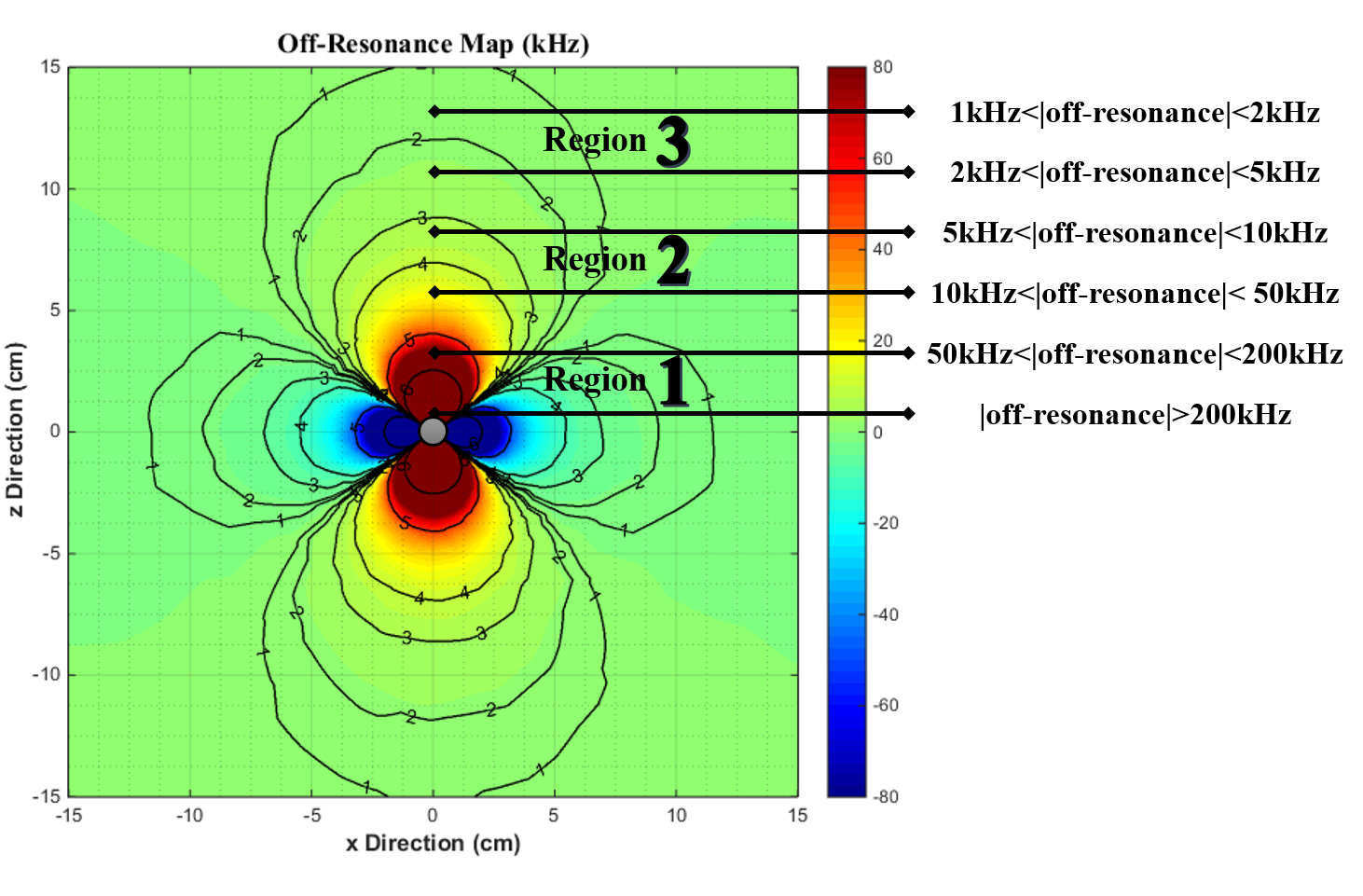
Corresponding frequency shift map caused by B0 field inhomogeneity around the ferromagnetic object was obtained and shown in Fig.1. At the close vicinity of the object (region 1), the off-resonance reaches several hundred of kHz. This area spans about 5 times the radius of the object.
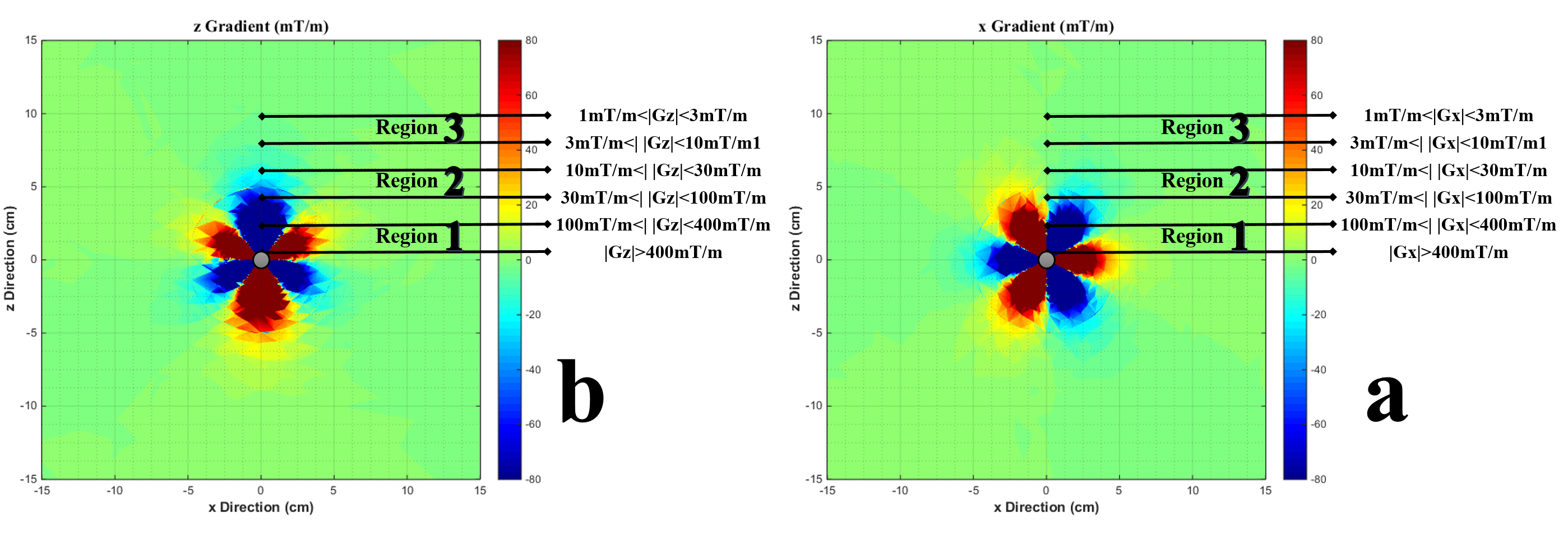
Fig.2 (a) and (b) depict the induced extra gradient field in x and z directions, respectively. It shows a region 2 where the induced gradients are in the range of scanner gradients used for imaging. The region 2 spans about 10 times the radius of the object.
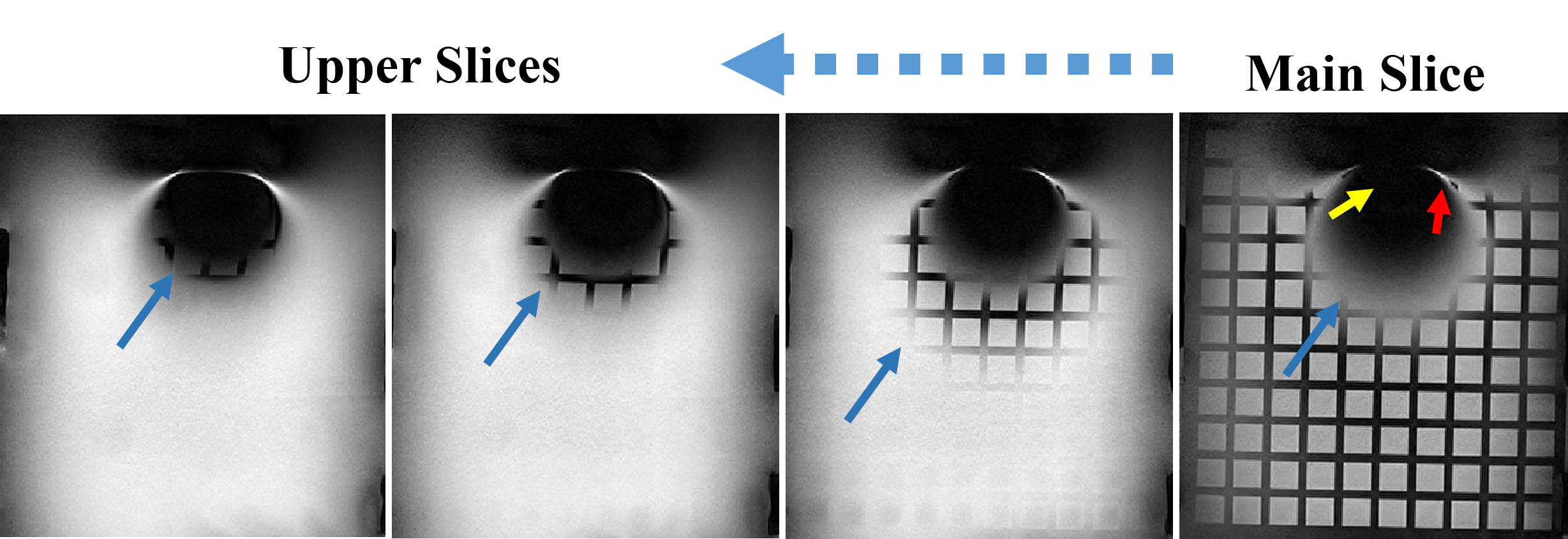
Fig.3 displays the experimental results for imaging a ferromagnetic material with spherical geometry. Fig.3 (a) shows the signal loss and overlap in the close distances (yellow and red arrows) and displacement in slice selection direction (blue arrow) in regions away from the object.
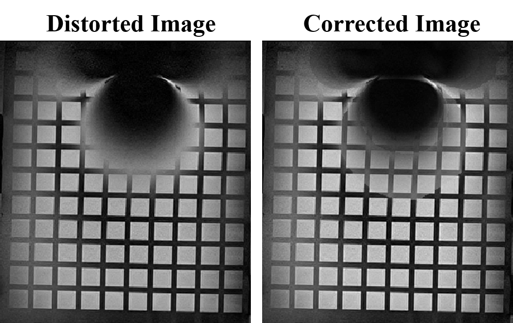
By using the mentioned formula and simulation the corresponding off-resonance map, the displaced regions can return to its original place. Fig.4 demonstrates the artifact correction results with the magnetic field mapping method for a sphere ferromagnetic foreign object that can represent a variety of different geometries4.
Discussion
The simulation results shown in Fig1, demonstrate the severity of frequency shift around a ferromagnetic object. In the aforementioned region 1, there is a signal loss caused by lack of the excitation in spins due to the huge off-resonance.
Most whole body MR scanners have maximum gradient strength in the range of 30-45 mT/m. In region 2, where the induced gradients are in this range, the linear frequency-position mapping becomes highly nonlinear. Therefore, the one-to-one mapping of frequency and position for spatial encoding can be violated and a signal pile-up occurs.
In region 3, farther than 10 times the radius of the ferromagnetic object, even though the extra induced gradient field is lower than scanner gradient, we have displacement in x (frequency encoding) and z (slice selection) directions. This displacement is smooth and does not result in any dislocation in the image. Therefore, its induced distortion can be corrected with post processing methods such as magnetic field mapping.
By using the mentioned formula and simulation the corresponding off-resonance map, the displaced regions can return to its original place as shown in Fig.4.
Conclusion
As a worst-case scenario, for regions farther than around 10 times the radius of a ferromagnetic foreign object, the post processing approach (based on the simulated off-resonance map) can be useful, even at 3 Tesla, to correct image distortions. At this distance, the exact shape of the object is not important and results obtained for the sphere, remain valid for most objects with the same volume.Acknowledgements
No acknowledgement found.References
[1] Lu, W., Pauly, K. B., Gold, G. E., Pauly, J. M., & Hargreaves, B. A. (2009). SEMAC: slice encoding for metal artifact correction in MRI. Magnetic resonance in medicine, 62(1), 66-76.
[2] Hargreaves, B. A., Worters, P. W., Pauly, K. B., Pauly, J. M., Koch, K. M., & Gold, G. E. (2011). Metal-induced artifacts in MRI. American Journal of Roentgenology, 197(3), 547-555.
[3] Smith, M. R., Artz, N. S., Wiens, C., Hernando, D., & Reeder, S. B. (2015). Characterizing the limits of MRI near metallic prostheses. Magnetic resonance in medicine, 74(6), 1564-1573.
[4] S. Amirrajab, V. Ghodrati, A. Nasiraei Moghaddam (2017). Main Factors in Estimation of Non-excitable area around ferromagnetic objects in MRI. European society of magnetic resonance in medicine and biology, 10.1007/s10334-017-0632-1.
Figures