2701
Unconventional trajectories on the Bloch Sphere: A closer look at the effects and consequences of the breakdown of the rotating wave approximation1Physics, University of Winnipeg, Winnipeg, MB, Canada, 2Laboratoire Kastler Brossel, ENS-PSL Research University, Paris, France
Synopsis
TRASE MRI uses rapid π-pulses of phase gradient fields, and in general requires as many as two distinct phase-gradient coils per encoding direction. This tends to restrict one to large amplitude, linear B1 fields, which in low B0 field leads to a breakdown of the rotating wave approximation. We have studied this regime both numerically and experimentally. Our results show a rich behavior involving a complex interplay of the Bloch-Siegert shift, the B1 start and stop phase, and B1 amplitude transients.
Introduction
TRansmit Array Spatial Encoding (TRASE) is a relatively new MRI method1,2 for which spatial encoding is achieved through the application of phase gradients of the B1 field – rather than magnitude gradients of the B0 field – and in general requires as many as two distinct phase-gradient coils per encoding direction. Moreover, traversal through k-space with TRASE requires a train of π-pulses generated by alternating phase-gradient coils. As a result, there is very strong motivation here to employ linear rather than rotating B1 fields (lest the already large number of rf coils should further double) and to understand the full details of rapid π-pulse generation with such fields. This is particularly important for our ongoing evaluation3,4,5 of the benefits and limitations of TRASE at low field, where the magnitude of the linear B1 field may not be negligibly small compared to B0 leading to a breakdown of the rotating wave approximation (RWA). Here we explore the unconventional trajectories on the Bloch sphere arising from the breakdown of the RWA. Our work reveals a complex interplay of Bloch-Siegert shift,6 B1 start or end phase,7 and B1 amplitude transients8 that must be taken into account to achieve the expected trajectory terminus.Methods
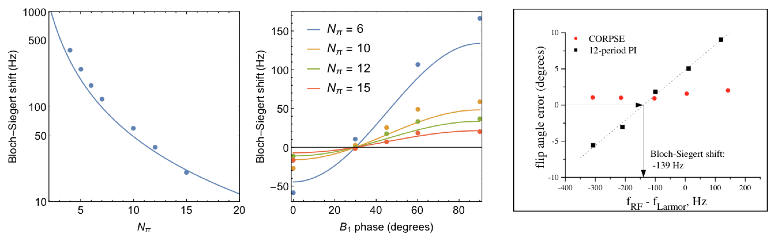
We studied the effects and consequences of the breakdown of the RWA through analytical and numerical solutions of the Bloch equations. For convenience, we express the magnitude of the B1 field as the parameter Nπ = B1/B0, which is the number of cycles of the oscillating field required to achieve a π-radian rotation. As such, the continuous wave Bloch-Siegert shift6 becomes ΔBcw = B0/(4 Nπ)2. For all simulations presented here, we fixed the B1 frequency to its nominal value ω0, applied rectangular pulses of linear field B1cos(ω0 t + φ) along the x-axis in the laboratory frame, and managed any de-tunings through a field shift δB away from B0. Experimental studies were performed in B0 fields of a few mT or less, using both water and hyperpolarized 3He gas samples.Results
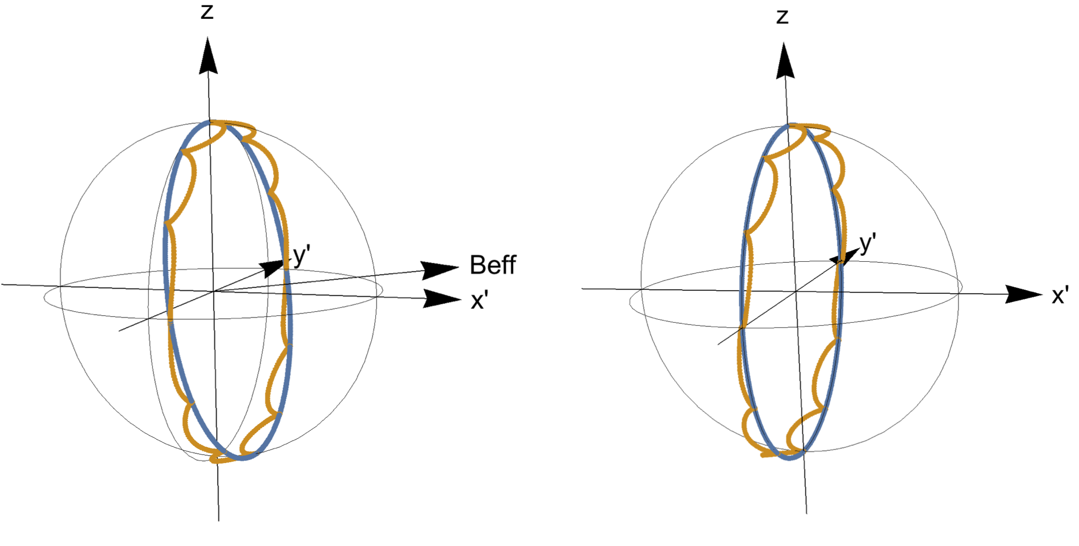
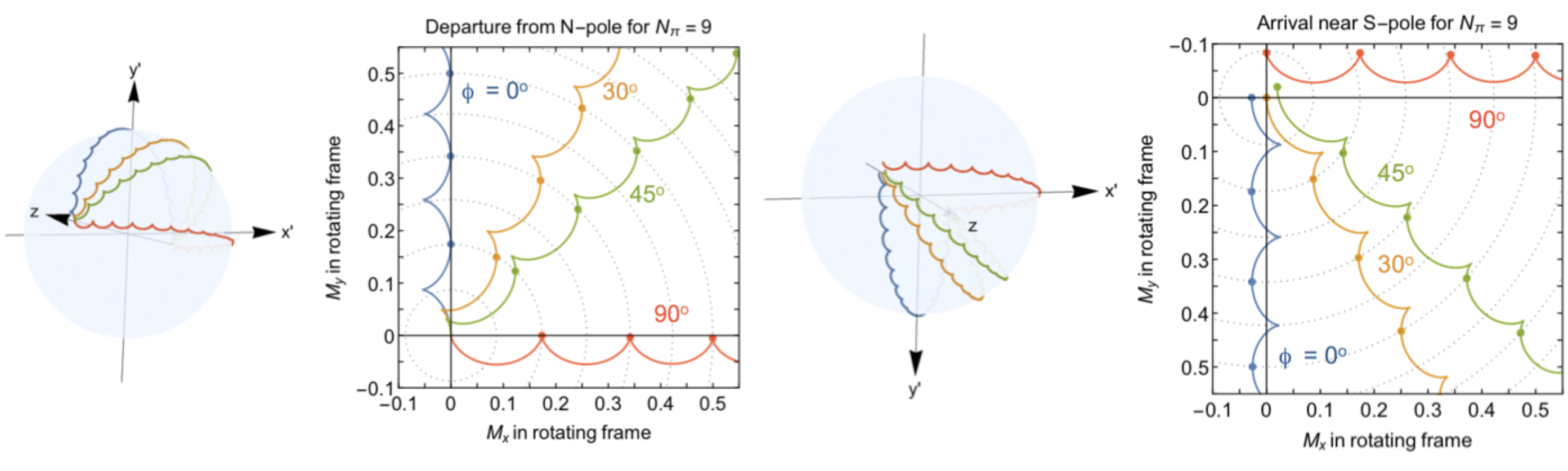
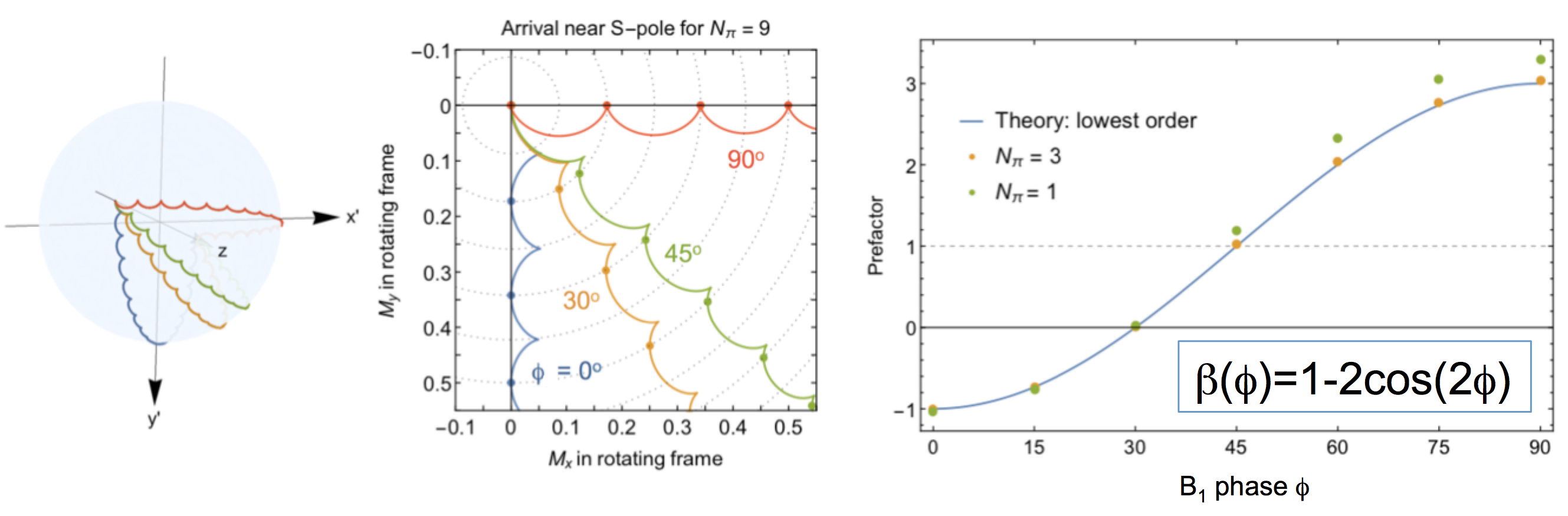
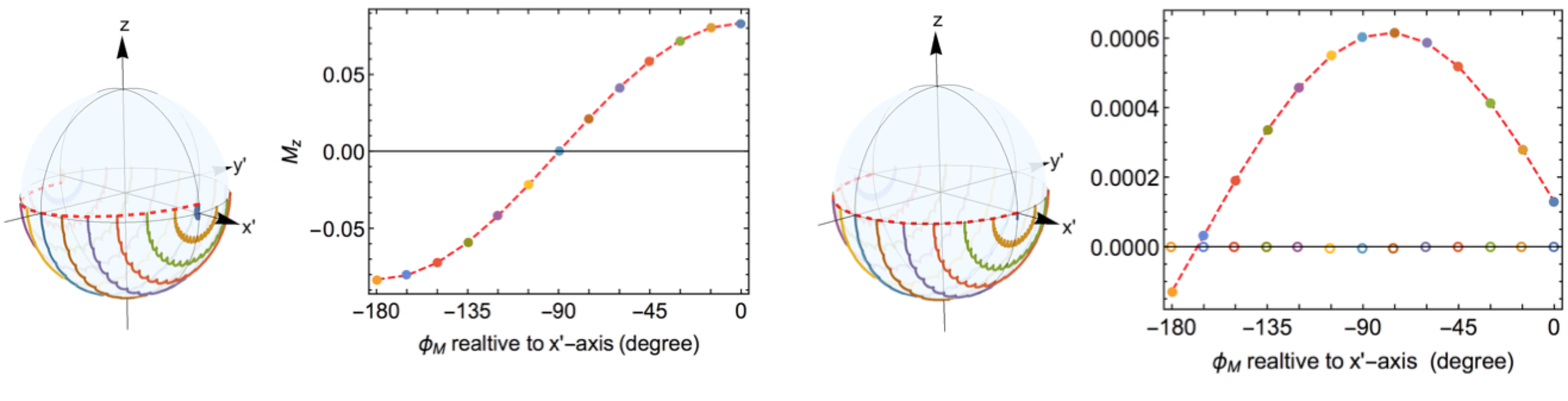
Numerical simulations are shown in Figures 1 through 4; experimental results are in Figure 5. Figure 1 highlights the general effects of the breakdown of the RWA due to a strong counter-rotating B1 field: the trajectory undergoes cycloid motion and a perfect π-pulse cannot be achieved without de-tuning the field. Every half-period, the trajectory without/with de-tuning lands on that due to a rotating B1 field with/without de-tuning of the same magnitude. Figure 2 highlights the fact that the specific details of the cycloid trajectory, and in particular its terminus, depends strongly on the phase of the B1 field. Starting and stopping pulses at the cusps in the trajectory (ie. zero field and zero coil current, occurring every half-period) is an important strategy for eliminating further complications due to B1 amplitude transients in real coils. As shown in Figure 3, a perfect π-pulse can always be achieved by de-tuning the field by δB = β ΔBcw, where to lowest order the prefactor β depends only on the phase φ. In Figure 4, we show the effect of the breakdown of the RWA on a π-pulse intended to rotate transverse magnetization about the x’-axis in the rotating frame. Again, the appropriate de-tuning of the static field will achieve the desired rotation. In Figure 5, we present a small compilation of experimental results achieved to date. In particular, we show data that confirms the 1/ Nπ2 behavior of the Bloch-Siegert shift, as well as the magnitude and change of sign of the prefactor β(φ). The Bloch-Siegert shift is determined experimentally as the de-tuning δB required to achieve a perfect π-pulse. We also present a comparison of the performance a composite π-pulse versus a simple rectangular π-pulse. Arbitrary pulse shapes and durations have also been investigated.Discussion and conclusion
We have made extensive numerical and experimental studies of the breakdown of the RWA due to a strong counter-rotating B1 field. Our results show a rich behavior involving the Bloch-Siegert shift, B1 start and stop phase, and B1 amplitude transient that is of fundamental interest in magnetic resonance. It is of great practical importance for low-field MR applications, in particular TRASE MRI where one is more or less restricted to using large amplitude, linear B1 fields. Achieving the expected trajectory terminus in this regime requires an appropriate phase-dependent de-tuning of the field. Using pulse durations and sequence timings that are half-integer multiples of the B1 period is also beneficial.Acknowledgements
References
1. JC Sharp, et al. Magn Reson Med. 2010; 63:151 and NMR Biomed. 2013;26: 1602.
2. Q Deng, et al. Magn Reson Imaging. 2013; 31:891.
3. PJ Nacher, et al. Proc ESMRMB 15, Magn Reson Mater Phy. 2015:28 Suppl.1;S64.
4. S Kumaragamage, et al. Proc ESMRMB 16, Magn Reson Mater Phy. 2016:29 Suppl.1;S34.
5. PJ Nacher, et al. This conference.
6. F Bloch and A Siegert. Physical Review. 1940;57:522.
7. D MacLaughlin. Rev Sci Instrum. 1970;41:1202.
8. M Mehring and J Waugh. Rev Sci Instrum. 1972;43:649.
Figures