2691
K-Space Trajectory Correction for UTE Sequence with Multi-Echo Radial Acquisition1Biomedical Engineering, Tsinghua University, Beijing, China, 2Gordon Center for Medical Imaging, Radiology, Massachusetts General Hospital, Harvard Medical School, Boston, MA, United States, 3Nuclear Medicine, West China Hospital, Sichuan University, Sichuan, China, 4Engineering Physics, Tsinghua University, Beijing, China, 5Key Laboratory of Particle and Radiation Imaging, Ministry of Education, Medical Physics and Engineering Institute, Tsinghua University, Beijing, China
Synopsis
UTE allows imaging of rapidly decaying short-T2 components and are often combined with
Introduction
Ultrashort Echo Time (UTE) imaging is widely used to image rapidly decaying short-T2 components such as tendon, ligament, bone, and lung tissue [1]. Especially, combination of UTE and multi-echo Dixon has been used for MR-based PET attenuation correction applications [2,3]. However, one of the major drawbacks of UTE is the inherent susceptibility to gradient errors due to the usage of radial acquisition [4]. When UTE is combined with multi-echo radial acquisition, especially with high gradient slew rate and amplitude, simple time delay corrections [5,6] render impractical to correct deviations from the ideal trajectory for each echo signals. In this work, we describe a simple, one-time calibration method that allows k-space trajectory correction for UTE sequence combined with multi-echo radial acquisition scheme. The performance of the proposed method is verified by acquiring a calibration scan from a water phantom and later applying the measured k-space trajectory information for reconstruction in a separate phantom and in vivo experiment.Methods
When spatial encoding is performed by the phase-encoding gradients, the spatially resolved signal at a spatial location x and time t can be expressed as follows [7,8]:
$$I(x,t) = \rho(x)\cdot e^{-i(\phi_{B_0}(t)+\phi_{G}(t))}$$
$$\phi_{B_0}(t)=\gamma\cdot\triangle B_0\cdot t$$
$$\phi_G(t)=x\cdot\gamma\cdot\int_{t_0}^{t}G(\tau)d\tau=2\pi\cdot x\cdot k_G(t)$$
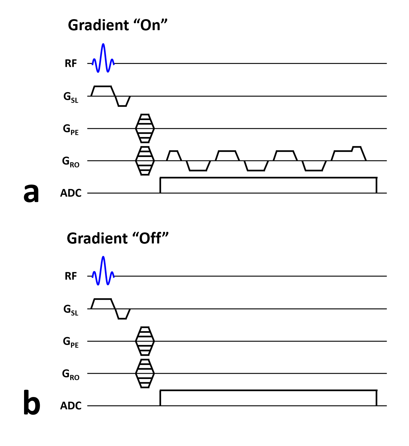
where $$$\rho(x)$$$ denotes the proton density, $$$\phi_{B_0}(t)$$$ denotes the phase accumulation due to field inhomogeneity ($$$\triangle B_0$$$ , $$$\gamma$$$ denotes gyromagnetic ratio, and $$$\phi_G(t)$$$ denotes the phase accumulation due to multi-echo gradient $$$G(t)$$$, and $$$k_G(t)$$$ denotes the k-space trajectory traversed by the multi-echo gradient. Thus, by acquiring scans with (Fig. 1a) and without (Fig. 1b) the multi-echo gradient, the phase accumulation due to field inhomogeneity ($$$\phi_{B_0}(t)$$$) can be eliminated and $$$k_G(t)$$$ can be derived via numerical fitting.
All experiments were performed on a whole-body PET/MR scanner (Biograph mMR, Siemens, Erlangen, Germany) using head coil for reception and body coil for transmission. 2D k-space trajectory calibration scan was performed on a water phantom to characterize the k-space trajectory traversed by a multi-echo UTE gradient sequence. The imaging parameters were: field-of-view (FOV) = 240 $$$\times$$$ 240 $$$mm^2$$$, matrix size = 128 $$$\times$$$ 256, slice thickness = 5 $$$mm$$$, TR/TE = 9.0/2.3 $$$ms$$$, and total scan time = 9 $$$min$$$ 50 $$$s$$$. The TR unit with (Fig. 1a) and without (Fig. 1b) the gradient structure of interest was acquired in an alternative fashion for each of the phase-encoding gradients.
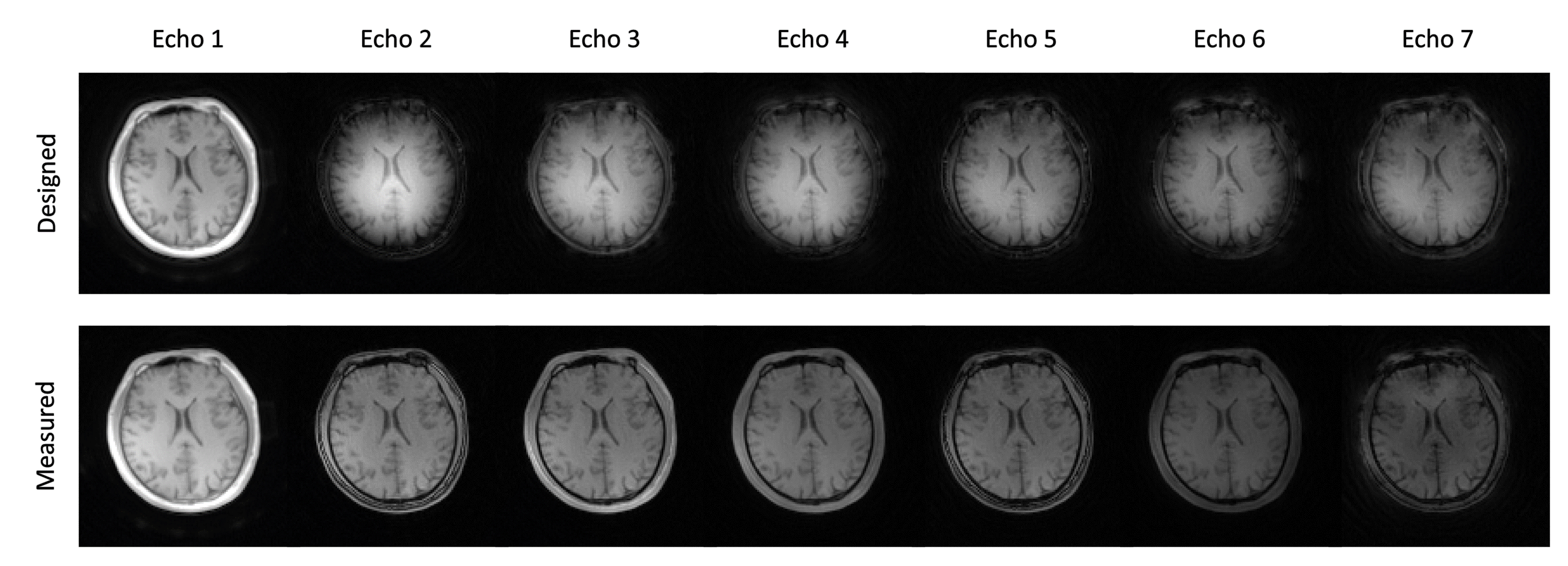
3D UTE with multi-echo radial acquisition was performed on a resolution phantom and a healthy subject. The study protocol was approved by our local Institutional Review Board (IRB). The imaging parameters were: field-of-view (FOV) = 240 $$$\times$$$ 240 $$$\times$$$ 240 $$$mm^3$$$, matrix size = 128 $$$\times$$$ 128 $$$\times$$$ 128, number of spokes = 51472, TR = 10.0 $$$ms$$$, TEs = 70/1830/2710/3590/4470/5350/6230 $$$\mu s$$$, flip angle = 10$$$^\circ$$$, hard pulse duration = 100 $$$\mu s$$$, gradient ramp time = 120 $$$\mu s$$$ (gradient slew rate = 163.1 $$$mT/m/ms$$$), plateau gradient amplitude = 19.57 $$$mT/m$$$, dwell time = 2.5 $$$\mu s$$$, and total scan time = 8 $$$min$$$ 35 $$$s$$$.Image reconstruction was performed using the k-space trajectory calculated from the designed gradient structure of multi-echo UTE and the k-space trajectory measured using the calibration scan as the input for non-uniform fast Fourier transform (NUFFT) reconstruction algorithm [9].
Results and Discussion
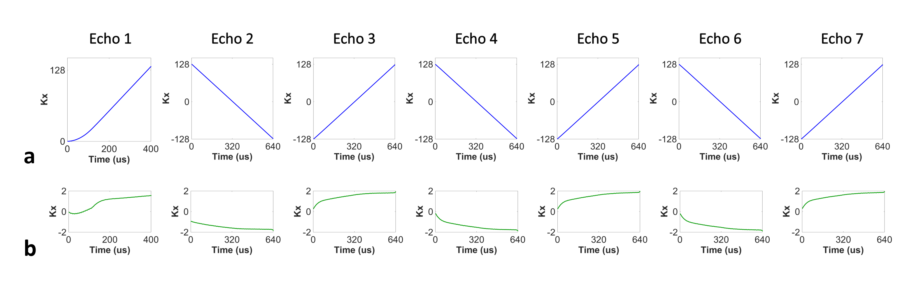
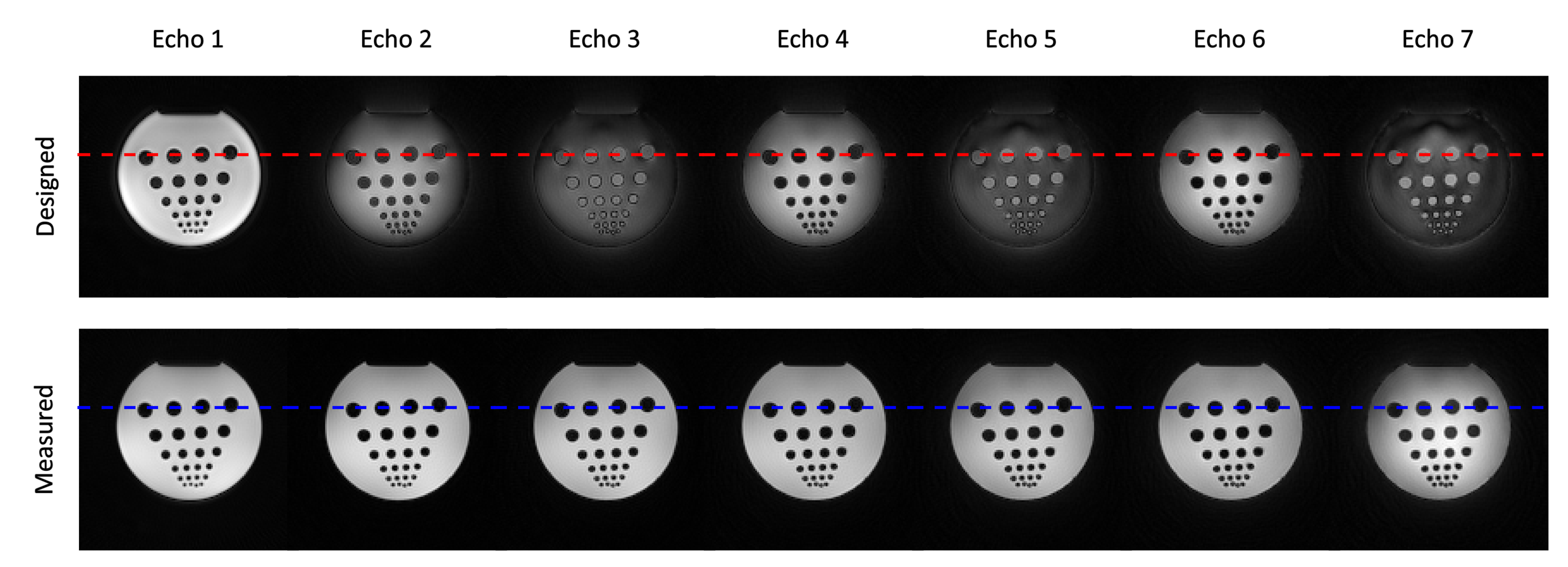
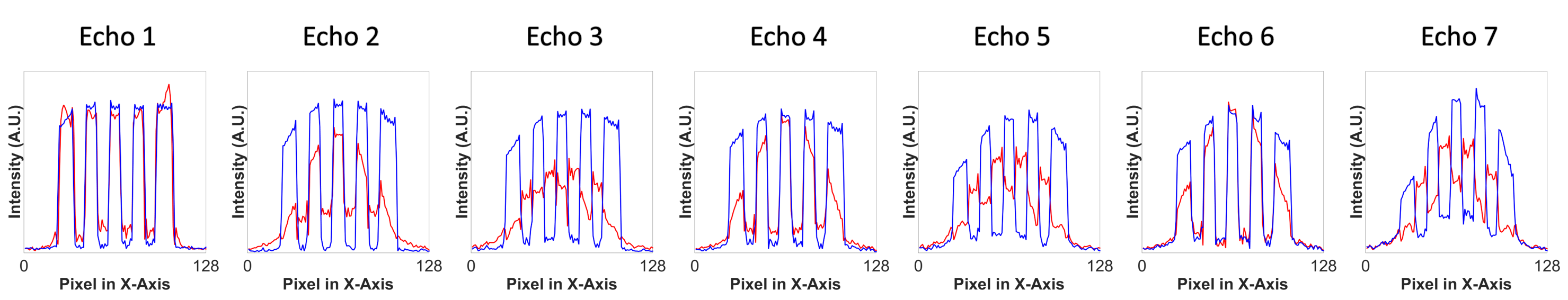
Clear differences were observed between the k-space trajectories calculated from the designed gradient structure and the k-space trajectories measured from the calibration scan using the proposed method (Fig. 2). Noticeably difference was observed between echoes, indicating unique k-space trajectory of each echo signal acquired in a multi-echo acquisition scheme (Fig.2b). The phantom experiment showed distortion artifacts in the images and signal profiles when k-space trajectory calculated from the designed gradient structure was used for image reconstruction (Figs. 3 and 4). These artifacts were significantly reduced when the measured k-space trajectory was used for image reconstruction (Figs. 3 and 4). The results from the in vivo experiment also showed significant reduction of distortion artifacts when measured k-space trajectory was used for image reconstruction (Fig. 5).Conclusion
We present a method that can be used to correct k-space trajectories in UTE sequence combined with multi-echo radial acquisition scheme. The proposed method can successfully reduce k-space trajectory-related distortion artifacts in UTE sequence combined with multi-echo radial acquisition.Acknowledgements
This work was partially supported by the National Institutes of Health (T32EB013180, R01CA165221, R21EB021710, and P41EB022544), National Natural Science Foundation of China (81471692), and Tsinghua Undergraduate Overseas Research Training Supporting Program (TOP OPEN).References
[1] Robson, Matthew D., et al. "Magnetic resonance: an introduction to ultrashort TE (UTE) imaging." Journal of Computer Assisted Tomography. 27(6): 825-846 (2003).
[2] Berker, Yannick, et al. "MRI-based attenuation correction for hybrid PET/MRI systems: a 4-class tissue segmentation technique using a combined ultrashort-echo-time/Dixon MRI sequence." Journal of nuclear medicine 53.5 (2012): 796-804.
[3] Jang, Hyungseok, et al. "Rapid dual‐echo ramped hybrid encoding MR‐based attenuation correction (dRHE‐MRAC) for PET/MR." Magnetic Resonance in Medicine (2017).
[4] Larson, Peder EZ, et al. "Ultrashort echo time and zero echo time MRI at 7T." Magnetic Resonance Materials in Physics, Biology and Medicine 29(3): 359-370 (2016).
[5] Speier, P., and F. Trautwein. "Robust radial imaging with predetermined isotropic gradient delay correction." Proceedings of the 14th Annual Meeting of ISMRM. 2006.
[6] Speier, P., and F. Trautwein. "A calibration for radial imaging with large inplane shifts." Proceedings of the 13th Annual Meeting of ISMRM. 2005.
[7] Alley, Marcus T., Gary H. Glover, and Norbert J. Pelc. "Gradient characterization using a Fourier‐transform technique." Magnetic resonance in medicine 39.4 (1998): 581-587.
[8] Duyn, Jeff H., et al. "Simple correction method for k-space trajectory deviations in MRI." Journal of Magnetic Resonance. 132: 150-153 (1998).
[9] Fessler, Jeffrey A., and Bradley P. Sutton. "Nonuniform fast Fourier transforms using min-max interpolation." IEEE Transactions on Signal Processing 51(2): 560-574 (2003).
Figures