2670
Concomitant B1 Field in Low-Field MRI: Potential Contributions to TRASE Image Artefacts1Department of Physics, University of Winnipeg, Winnipeg, MB, Canada, 2Laboratoire Kastler Brossel, ENS-PSL Research University, CNRS, UPMC-Sorbonne Université, Collège de France, Paris, France
Synopsis
TRansmit Array Spatial Encoding (TRASE) MRI uses trains of rf pulses produced by transmit coils which generate transverse fields of uniform magnitude and spatially varying directions. These coils also unavoidably generate concomitant rf fields, which in turn affect magnetisation dynamics during rf flips in low-field NMR. Bloch’s equation are numerically solved to show that π-pulses imperfectly reverse transverse magnetisation and that the resulting error in azimuthal angle linearly increases with B1/B0, with the number of pulses in the TRASE pulse train, and with distance from the coil axis in the sample. This may induce significant image distortions or artefacts. Supporting experiments performed at 2 mT will be reported.
Introduction
TRansmit Array Spatial Encoding (TRASE)1,2 is a pulsed MRI technique that involves B1-field phase gradients for rf excitation and k-space traversal within echo trains. Dedicated transmit coils and repeated series of π-pulses with positive and negative phase gradients are needed for image acquisition. Ideal phase gradients correspond to uniform B1 magnitude in the transverse plane and linear variation of B1 direction along the encoding axis. With careful transmit coil design, the target homogeneity of B1 amplitude can be achieved. But, to accommodate for changes in B1 orientation, concomitant rf field components necessarily exist. For a z-axis phase gradient, for instance, the leading concomitant component (B1z) can be expected to have a negligible contribution to the rf-driven evolution in high field and may simply contribute to rf power deposition.2 In contrast, time evolution in low field, where B1 magnitude is not much smaller than B0, may be influenced both by the counter-rotating component of an oscillating transverse field3 and by the concomitant component B1z. Here we analyse the NMR dynamics and focus, in particular, on the deviations in time evolution that occur for one or several π-rotations applied by spiral transmit coils designed for TRASE imaging.4,5Methods
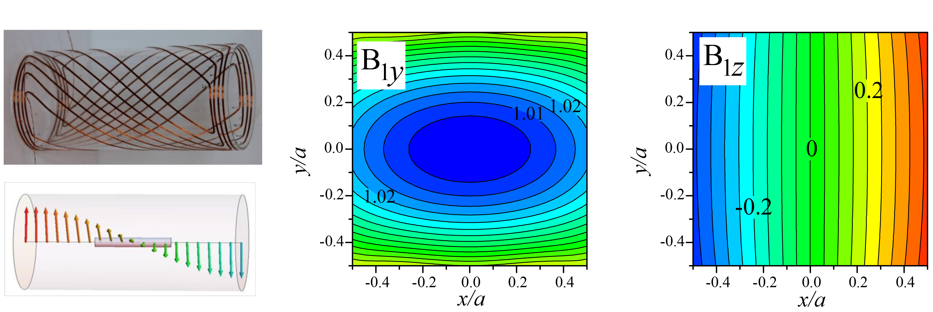
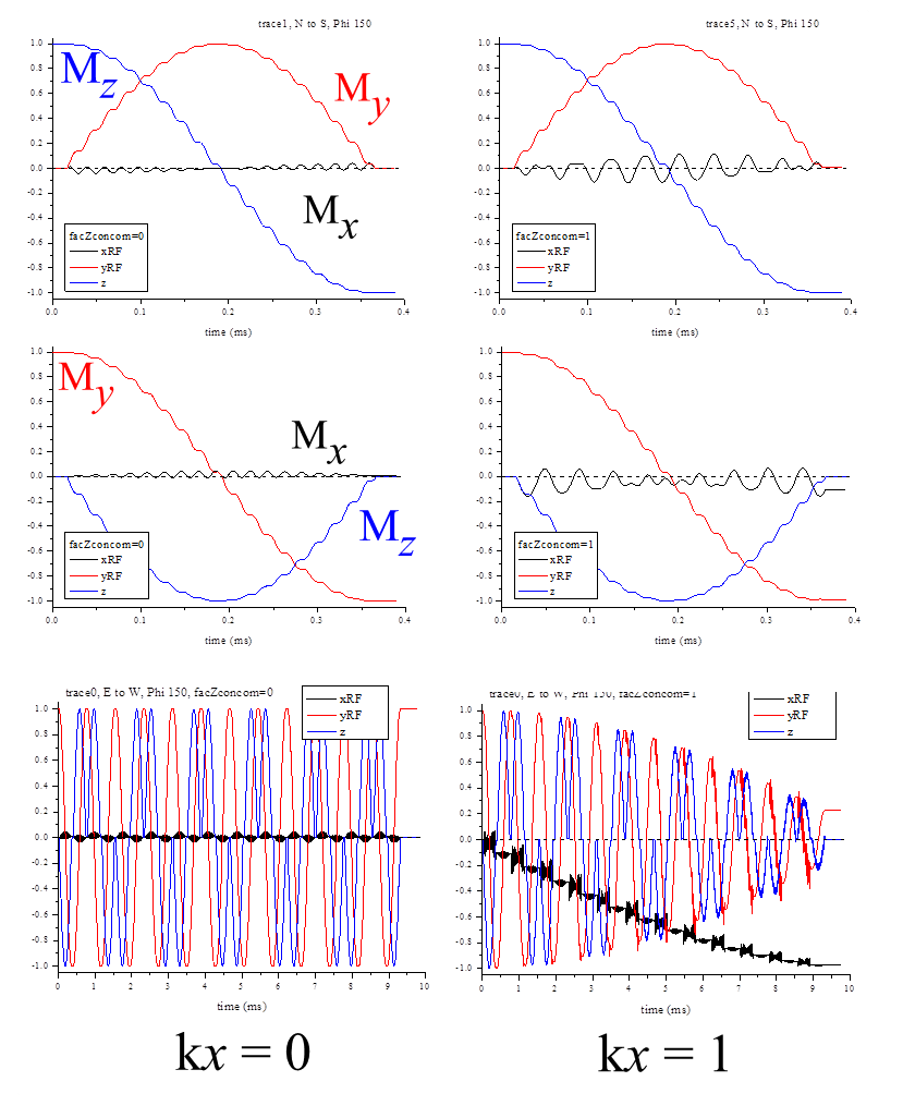
Numerical solutions of Bloch’s equation are computed using compiled C or Mathematica programs for a simple analytical model (a field of perfectly uniform transverse magnitude) and for the exact field map of the transmit coil used in current low-field TRASE studies5 (Fig. 1). Different types of rf pulses and pulse sequences are considered, acting either on longitudinal or transverse magnetisation. Emphasis is placed on resonant and near-resonant inversion pulses, for which the influence of pulse shape and duration is investigated. Experimental tests on thermally polarised imaging phantoms (slab-shaped containers filled with doped water) are under way at 2 mT (83.682 kHz). Assessments are performed for series of π-pulses from spiral coils with a combination of techniques, such as usual 2D imaging (with B0-field magnitude gradients) or phase mapping by NMR interferometry.6Results
Figure 1 shows a prototype spiral coil and displays computed field maps. The helicoidal field pattern has a linear z-dependence of its phase φ(z)=k z (with a pitch coefficient k=0.12 cm-1) and a fairly uniform magnitude of the transverse component, B1t (aligned with the y-axis, at the coil centre). The (mainly) x-dependent concomitant rf field component, B1z(x) = k x B1t, satisfies the rot(B1)=0 Maxwell’s equation under the assumption of perfectly uniform B1t. However, this approximation breaks down for distances from the z-axis of order a/2 and the actual field maps, which satisfy both rot(B1)=0 and div(B1)=0, are needed for reliable NMR simulations. Figure 2 displays magnetisation trajectories (in the rotating frame) during rf π-pulses computed for sample elements in the z=0 plane, lying either on the coil axis (left: x=0; hence, B1z=0) and off axis (right: k x =1 = B1z/B1t, chosen for clear effects). They allow for a comparison between evolution perturbed by the counter-rotating component alone (see3 for further details) or in combination with the concomitant component B1z. In both cases, the trajectory features depend on the initial magnetization state. On axis, in spite of deviations from rotating wave approximation (RWA) trajectories, perfect inversion is achieved. Off axis, B1z yields deviations with distinct time variation and maximal amplitudes but, most notably, induces a phase shift α for the East-West trajectory endpoint. This shift increases with B1 magnitude and distance from the spiral coil axis and is found to amount to α = α0 k y/Nπ, where α0 = 58° and Nπ = B1t/B0 is the ratio between the π-pulse duration and the rf period. As a result, for a TRASE phase-encoding sequence comprising tens of pulses, the expected cumulated added rotation can exceed 90°.
Discussion
In TRASE MRI, trains of PI pulses from a pair of coils are expected to create magnetisation patterns which only depend on the geometry of the coils, e.g., only depend on z for spiral coils such as in Fig.1 (x or y dependence may also be achieved, for instance with "Maxwell-type" coils2). However, we have shown that the concomitant rf field B1z modifies the phase pattern imprinted on the transverse magnetization in such a way that, to first order, geometrical planes where phase is uniform are no longer perpendicular to the encoding direction but tilted. This tilt, which linearly increases with the field intensity ratio B1/B0, may induce significant image distortions or artefacts, an issue which will need to be addressed.Acknowledgements
Support from CNRS and ENS for joint work is gratefully acknowledged (CP B.).References
1. JC Sharp et al., Magn Reson Med 63:151 (2010); NMR Biomed, 26: 1602 (2013).2. Q Deng et al., Magn Reson Imaging 31:891 (2013).
3. CP Bidinosti et al, this conference
4. CP Bidinosti et al., Proc. ISMRM 18 (2010) p. 1509.
5. P-J Nacher et al., Proc ESMRMB15, Magn. Reson. Mater. Phy. 28 Suppl. 1 (2015) p. S64.
6. L Darrasse et al., Magn Reson Imaging 5:559 (1987).
Figures