2663
Properties optimization of pads configurations on CST to minimize B1+ field inhomogeneities at 7T in the temporal lobes and cerebellum1CEA-Neurospin, Paris, France, 2Institut Fresnel, Marseille, France, 3CEA-Le Ripault, Monts, France
Synopsis
A simple and efficient way to enhance the B1+ field dark areas appearing in the temporal lobes and cerebellum at 7T in MRI is to use pads with relative High-Dielectric Constant materials. We present here simulations of different pads configurations aiming to reduce those dark areas. It has been found that the educated guess consisting in using a three pads configuration localized in front of each area is less efficient than two pads above the ears for the temporal lobes or a single pad on the neck for the cerebellum.
Introduction:
One way to address the B1+ inhomogeneity in ultra-high field MRI (B0≥7T) is the use of relative High-Dielectric Constant (HDC) materials in radiofrequency (RF) coils [1]. Their high displacement current alters the global RF distribution in the transmit coil and generates a secondary localized RF field used to tune the B1+ field. In order to increase it in both temporal lobes and cerebellum which are the most altered areas at those fields [2] labeled in the following as “dark areas”, number, location, size, geometry and permittivity of pads were optimized. We demonstrate through simulations that the most intuitive approach consisting of setting pads in front of each weak regions does not lead to the most efficient outcome.Materials and Methods:
We aimed to minimize the volumes where the B1+ field is too low compared to the target and to optimize pads distribution around the head. To that end, we proceeded as followed:
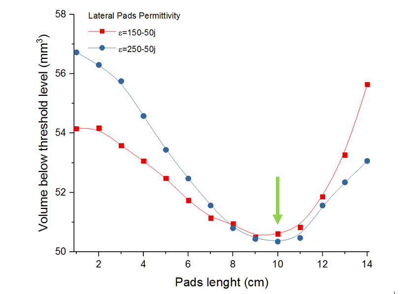
- First, on a single pad, we assess, for a fixed pad thickness as a consequence of limited space in the birdcage, the influence of its surface on local B1+ right in front of the pad for several couples of ε’/ε’’ (150/50;250/50), achievable with classic HDCs while keeping a softy texture [3].
- Then, following an educated guess, using the optimized pad settings, two and three pads scenarii were tested to mitigate simultaneously as much as possible the most degraded areas.
Whole study has been carried out with CST Microwave Studio (Computer Simulation Technology, Framingham, MA) which was used to compute B1+ maps (Computer Simulation Technology, Framingham, MA) of a specific anthropomorphic mannequin (SAM; ε’=42; ε’’=60) in a shielded birdcage head coil. The coil used is a shielded high pass birdcage with 16 strip legs of 1 cm width and 22 cm height and 5.2 pF capacitors. The shield diameter is 31 cm and the birdcage diameter is 26 cm. The simulated birdcage was designed to resonate, when loaded, at 298 MHz which is the Larmor frequency of our 7T MRI scanner. All simulations were done without additional tuning or matching circuits. B1+ maps were normalized for a stimulated power of 1 W. To better evaluate the benefit of padding, a threshold corresponding to 50% of the maximum B1+max field in the center of the head in the case without pads was chosen and pads performance were quantified through the volume increased above that threshold. A brain mask was obtained from a 7T 3D 1 mm isotropic MPRAGE volume using FSL pipeline, scaled to the SAM phantom skull dimensions and used to present the performance results on the focused areas.
Results:
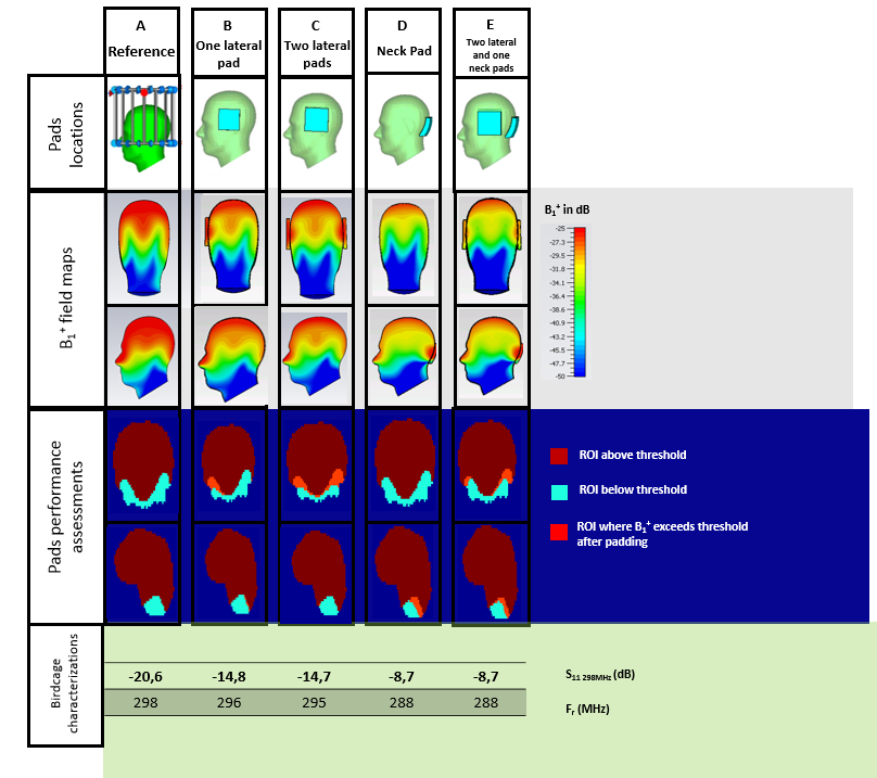
Figure 1 shows the volume evolution where the field is lower than threshold level in the case of lateral pads. It can be seen that for each permittivity level, the optimized sizes are around 9x9 cm² to efficiently reduce the dark area localized in the temporal lobes. Figure 2 shows performances, pads geometry and field distribution for 4 scenarii. Corresponding coil tune (S11 parameters at 298 MHz and resonance frequencies) are also presented.Discussion:
It can be seen that the educated guess consisting in adding a pad in front of the temporal lobes and the cerebellum to illuminate those areas does not lead to the best setting (Figure 2.E). Indeed, two lateral pads display better performance on the temporal lobes than three pads (Figure 2.C). In the cerebellum, for the selected neck pad, the field illumination is not deep enough to expect a better contrast on the image (Figure 2.D and 2.E). An explanation to this unsatisfying result is that as the lateral pads are far from the birdcage strips, they do not detune the coil (Figure 2 last row) contrary to the pad on the neck which also impact its performance. It must be kept in mind that, due to the lack of space in the back of the head, there is almost no degree of liberty on the neck pad to improve its penetrating effect in the cerebellum. Consequently, issues on temporal lobes and in the cerebellum cannot be treated simultaneously with our 3 pads setting. We did not investigate further effects of pads having different sizes and permittivity at other locations which may be interesting as future studies.Acknowledgements
This work has been supported by the Programme Transversal du CEA and the FET-OPEN M-CUBE Project.References
[1] Webb and al., Concepts Magnetic Resonance, 38,148–184.
[2] O’Reilly and al., Journal of Magnetic Resonance, 2016, 270, 108-114.
[3] A. L. Neves and al., Magnetic Resonance in Medicine, 2017 (ahead of print).
Figures