2646
Evaluation of spiral trajectories for very low field MR imaging of the brain1Medical Imaging Research Centre, Dayananda Sagar Institutions, Bangalore, India, 2Dept. of Radiology, Columbia University Medical Center, New York, NY, United States
Synopsis
Very low field (VLF) MRI systems provide
Motivation
Very low field (VLF) MRI systems provide accessible solutions for brain imaging and is an active area of research1,2. Spiral acquisition provides significant advantages over Cartesian trajectory through efficient sampling resulting in higher signal-to-noise ratio (SNR). In this work, spiral trajectory was designed for 10 mT without violating the constraints maximum gradient amplitude (Gmax) and maximum slew rate (SRmax). This was performed to evaluate the utility of spiral imaging at VLF MRI.Approach
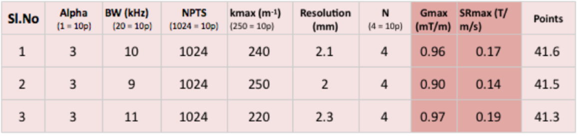
A spiral trajectory was designed using equation (1)3 $$k=\lambda\tau^\alpha e^{j\omega\tau} .. (1)$$ where $$$\lambda$$$ is maximum extent of k-space, $$$\tau$$$ is a function of time t and is defined as $$$\sqrt(t)$$$, $$$\alpha$$$ defines the density factor ($$$\alpha$$$=1, Archimedean and $$$\alpha$$$>1, VDS), $$$\omega$$$ is number of cycles, defined as $$$2\pi n$$$. The k-space spiral trajectory was designed based on two hardware constraints of maximum gradient amplitude Gmax =1mT/m and maximum slew rate SRmax = 0.7T/m/s for VLF-MRI. The trajectory was optimized based on parameters α, maximum k-space extent (kmax), number of points, $$$\omega$$$ and bandwidth. A lookup table was generated by varying $$$\alpha$$$ and $$$\omega$$$ from 1 to 4, kmax varied from 200m-1 to 250m-1, number of points – 512, 768 and 1024 and bandwidth 5 to 20kHz difference of 1kHz. These spirals were graded based on a points (p) system shown in Table 1 and the top three were selected for further analysis. A human brain image acquired from 1.5T Siemens Avanto scanner with parameters: matrix size–128x128, slice thickness–4mm, TR/TE–4000/99ms, was used as the test data. Gaussian noise corresponding to SNR were added to simulate noisy data. 16 shots VLF VDS was used to reconstruct brain retrospectively by using Non uniform Fast Fourier Transform (NuFFT) and compared with Cartesian reconstruction (figure 2). Gradient Recalled Echo (GRE) sequence was designed using Pulseq4 for spiral and Cartesian trajectories to compare acquisition times as shown in figure 3. The parameters for GRE were FOV-270mm, TR/TE–60/10ms for spirals and 14/8ms for Cartesian trajectory, bandwidth–10kHz matrix size-128x128 and 16 shots, each of 1024 points were considered for spiral trajectory. Retrospective reconstructions were also performed on human brain by using Graphical Programming Interface (GPI) lab5. Images with five different SNRs were reconstructed using GPI and compared with reconstruction using NuFFT. SNRs for all the reconstructed images were calculated.Gains and Losses
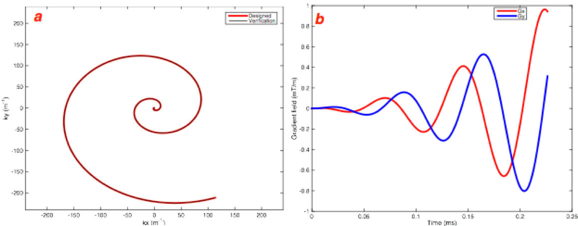
VLF MRI employing VDS based trajectory acquisition provides for accelerated imaging. The designed k-space spiral trajectory for low-field MRI (10mT) along with analytical method validation is shown in figure 1 (a) and corresponding gradient waveforms are shown in 1(b) with Gmax-0.96mT/m and SRmax-0.17T/m/s. These demonstrations illustrate the gains of improved and efficient signal sampling through spiral imaging meeting the needs of hardware constraints. Significant improvement in the performance could be accomplished with increased slew rate to reduce the number of shots and hence the total acquisition time. A significant loss is the requirement of increased averaging at VLF to allow for acceptable image quality. Retrospective preliminary data
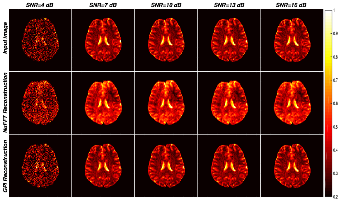
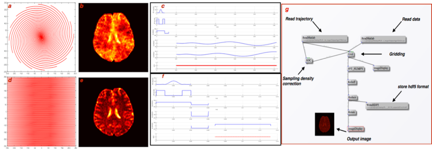
Figure 2 shows the image reconstruction for various SNRs using NuFFT and GPI lab. It can be observed that the reconstructions are comparable and perform reasonably above 10db SNR. Figure 3 shows the comparison of brain image (SNR = 16dB) reconstruction using VDS trajectory (16 shots) with Cartesian trajectory along with potential pulse sequences from Pulseq-GPI6 for an identical number of data points. The total acquisition time for VDS-GRE was 960ms while that for Cartesian trajectory was 1792ms. The figure demonstrates the implementation capability of the proposed approach. The GPI network utilized for image reconstruction is shown in figure 3(g). Impact
VLF-MRI requires a compact hardware system (portable and accessible) at low cost. Acquiring the data through spiral trajectory results in accelerated acquisition. There is a reduction by a factor of 1.8 in the acquisition time compared to the Cartesian case. From figure 3, it can be seen that images reconstructed using spiral trajectory was smoother than the Cartesian trajectory images for various SNRs as spiral trajectory at such target resolutions would not cover the corners of the k-space unlike the Cartesian trajectory. Conclusion and Future work
VLF (10mT) spiral trajectory was designed within stringent hardware constraints. It can be therefore concluded that spiral trajectories might offer an exciting prospect at VLF MRI. Retrospective reconstruction of brain images was performed for various SNR images using NuFFT and GPI. Future work involves incorporating relaxometry values for brain at 10mT (in low field simulator software7) to assess the spirals and prospectively implement on a home built scanner being currently pursued.Acknowledgements
This work was supported by grant funding from DST/VGST/KFIST/LII/GRD333.References
[1] Mathieu Sarracanie, et al., Low-Cost High-Performance MRI, Sci Rep. 2015 Oct 15;5:15177. [2] Cooley CZ, et al.,Two-dimensional imaging in a lightweight portable MRI scanner without gradient coils, Magn Reson Med. 2015 Feb;73(2):872-83. [3] Bénédicte M.A, et al., Spiral demystified, Magn Reson Imaging. 2010 Jul;28(6):862-81. [4] Kelvin J. Layton, et al., Pulseq: A Rapid and Hardware-Independent Pulse Sequence Prototyping Framework, Magn Reson Med 2016 Jun 7. Epub 2016 Dec 7. [5] Nicholas R. Zwart et. al.,Graphical Programming Interface: A Development Environment for MRI Methods, Magn Reson Med., 10.1002/mrm.25528. [6] Keerthi Sravan R, et. al. Implementation of Pulseq in GPI Lab. 2017; ISMRM. [7] Wu Z, Chen W, Nayak KS, Minimum Field Strength Simulator for Proton Density Weighted MRI. PLoS ONE 11(5): e0154711. doi:10.1371/journal.pone.0154711,2016.Figures