1895
A phantom set-up to evaluate slow flow artefacts in vessel wall MRI of intracranial aneurysms1Biomedical engineering and physics, AMC, Amsterdam, Netherlands, 2Radiology and Nuclear Medicine, AMC, Amsterdam, Netherlands, 3MIRA Institute for Biomedical Engineering and Technical Medicine, University of Twente, Enschede, Netherlands, 4Biomedical Sciences, VU university, Amsterdam, Netherlands
Synopsis
To reliably assess the vessel wall, adequate blood suppression is of high importance. Most black-blood vessel wall MRI sequences rely on flow sensitive signal attenuation. Intra-aneurysmal flow is often chaotic with slower flows near the aneurysm wall. Therefore, certain regions within the aneurysm might be more difficult to suppress. In this study we developed a phantom set-up to evaluate slow flow artefacts in vessel wall MRI of intracranial aneurysms. This setup allows to study the sensitivity of different vessel wall MRI sequences (e.g. DANTE, MSDE, 3D TSE) in relation to specific aneurysm geometries and contrast agent concentrations.
Introduction:
Vessel wall MRI is increasingly used as a clinical tool for evaluating wall thickness in intracranial aneurysms.[1,2] Additionally, vessel wall enhancement could be evaluated after contrast administration, reflecting various aspects of aneurysm pathology, such as inflammation. Previous studies have shown that wall enhancement helps to identify ruptured aneurysms in patients with subarachnoid haemorrhage and multiple aneurysms.[2] Some unruptured aneurysms also show wall enhancement, which might indicate instability.[3–5] To reliably assess the degree of vessel wall enhancement, adequate blood suppression is of high importance. This has led to the development of multiple black-blood vessel wall MRI sequences.[1,6,7] Most of these methods rely on flow sensitive signal attenuation. Intra-aneurysmal flow is often chaotic with slower flows near the aneurysm wall. Therefore, certain regions within the aneurysm might be more difficult to suppress. This could lead to 'pseudo' wall enhancement and misinterpretation of the aneurysm stability. It is therefore important to assess the performance of vessel wall MRI sequences in a controlled setting with different aneurysm geometries and contrast agent concentrations. The aim of this study was to create such a phantom set-up accurately mimicking aneurysm geometries for evaluating slow flow artefacts from vessel wall MRI.Methods:
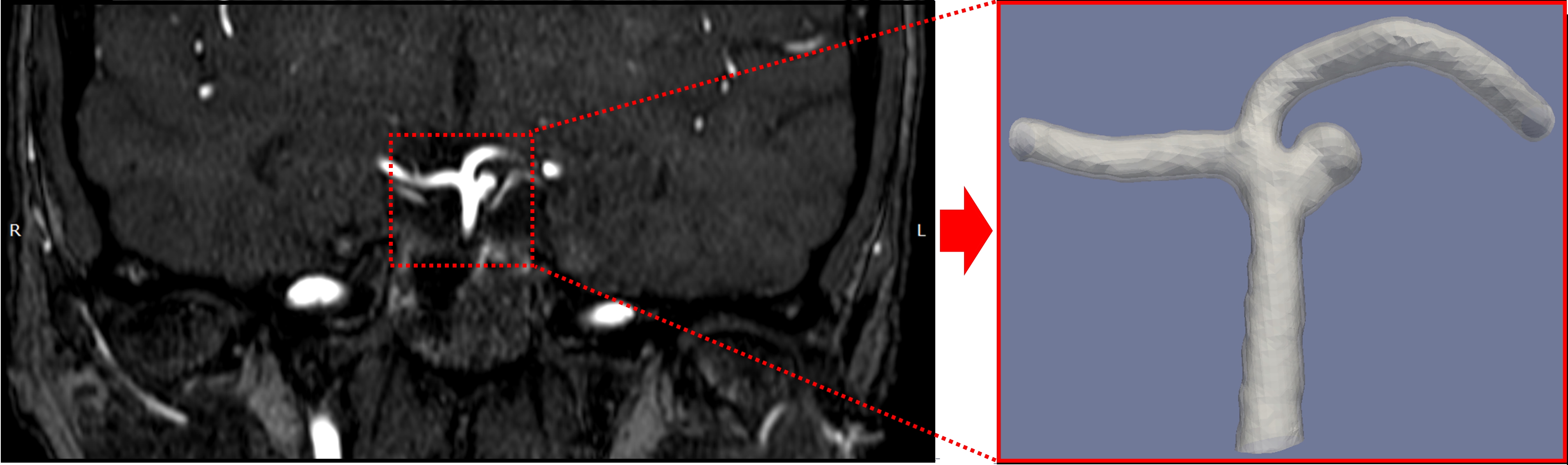
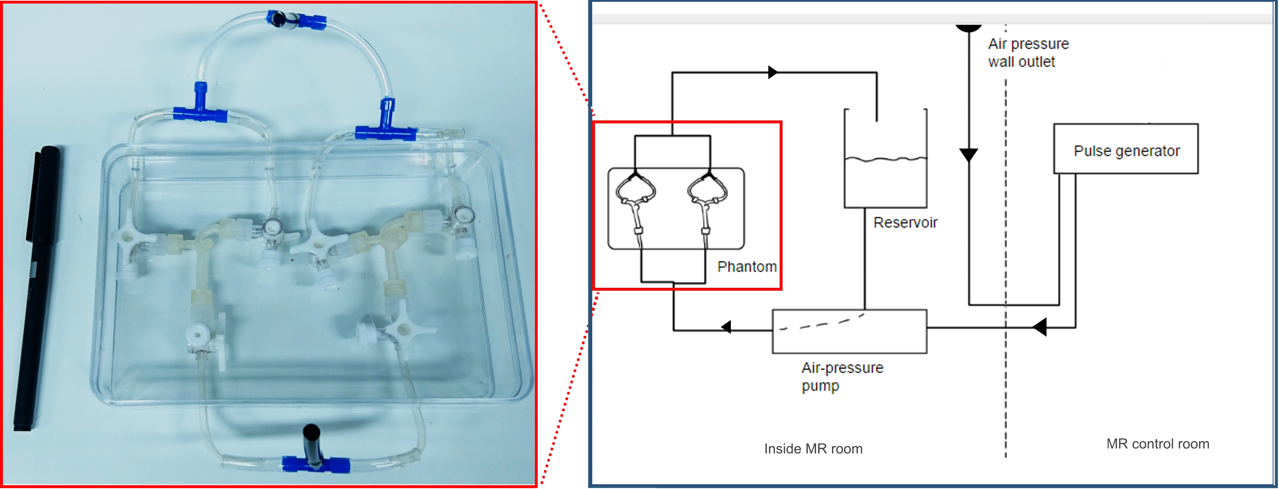
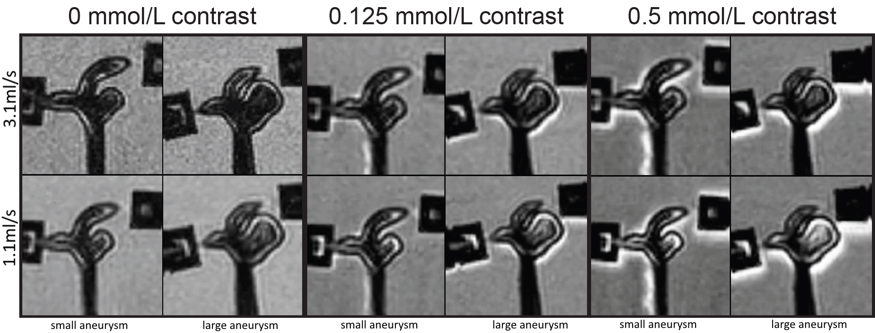
Two 3D printed vascular models were generated based on 3T TOF-MRA data of a single patient with an intracranial aneurysm, see Figure 1. The first phantom includes the actual aneurysm, with a diameter of 7.5mm. For the second phantom, the aneurysm was adjusted to reduce the maximum diameter to 3.5mm. The phantom was connected to a pulsatile flow pump (Figure 2). Imaging was performed on a 3.0-T MR system (Philips Healthcare, the Netherlands) using a 16-channel SENSE head coil. For this feasibility study, we chose a 3D VISTA vessel wall MRI sequence (Philips Healthcare, the Netherlands) with the following parameters: TR/TE = 1500/31.7 ms, TSEfactor = 56, resolution = 0.7mm isotropic, acquisition time = 10 min. We performed measurements using three different concentrations (0, 0.125 and 0.5 mmol/l) of gadobutrol (Gadovist, Bayer BV, Netherlands). The highest concentration corresponds to the recommended concentrations in vivo. At each concentration, two flow settings (1.1ml/s and 3.1ml/s), which correspond to physiological flow range, were used. Finally, a computational fluid dynamics (CFD) analysis was performed to evaluate flow characteristics in the aneurysm using fluent (Ansys, USA).Results:
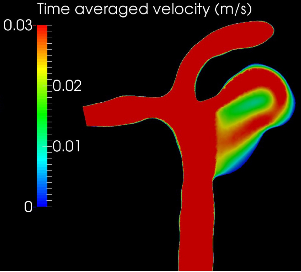
Good flow suppression was obtained for the feeding parent artery. However, in both aneurysms at all scan conditions, a higher signal intensity was observed (Figure 3), which increased with increasing contrast agent concentrations. Moreover, the observed high signal intensities were predominantly near the aneurysm wall as well as in the centre of the aneurysm lumen, which corresponded with areas of low velocity on CFD (Figure 4). In the presented setup, we noticed some leakage of contrast agent near the connectors, influencing the agar signal but not the signal within the aneurysm. This has been prevented in our current set-up.Discussion
We presented a set-up to evaluate slow flow artefacts vessel wall MRI of intracranial aneurysms. Our data shows that slow flow artefacts can mimic aneurysm wall and wall enhancement, as the effect increases with contrast concentration. In in vivo aneurysm imaging this signal could be falsely interpreted as a thicker or enhanced wall. Therefore, aneurysms might be erroneously categorised as unstable. Although our current study used a specific vessel wall imaging sequence (variable flip angle TSE), our set-up can be used to study the effect of variations in sequences and parameters and to design new sequences with better flow suppression characteristics.Conclusion:
A patient-specific phantom set-up was developed to evaluate slow flow artefacts in vessel wall MRI of intracranial aneurysms. This setup allows to study the sensitivity of different vessel wall MRI sequences (e.g. DANTE, MSDE, 3D TSE) for generating slow flow artefacts in relation to specific aneurysm geometries in more detail.Acknowledgements
No acknowledgement found.References
1. de Havenon A, Chung L, Park M, Mossa-Basha M. Intracranial vessel wall MRI: a review of current indications and future applications. Neurovascular Imaging. 2016;2(1):10.
2. Mandell DM, Mossa-Basha M, Qiao Y, et al. Intracranial Vessel Wall MRI: Principles and Expert Consensus Recommendations of the American Society of Neuroradiology. AJNR Am J Neuroradiol. 2016.
3. Hu P, Yang Q, Wang DD, Guan SC, Zhang HQ. Wall enhancement on high-resolution magnetic resonance imaging may predict an unsteady state of an intracranial saccular aneurysm. Neuroradiology. 2016:1-7.
4. Edjlali M, Gentric JC, Régent-Rodriguez C, et al. Does aneurysmal wall enhancement on vessel wall MRI Help to distinguish stable from unstable intracranial aneurysms? Stroke. 2014;45(12):3704-3706.
5. Backes D, Hendrikse J, van der Schaaf I, et al. Determinants of Gadolinium-Enhancement of the Aneurysm Wall in Unruptured Intracranial Aneurysms. Neurosurgery. 2017;0(0):1-7.
6. Wang J, Yarnykh VL, Yuan C. Enhanced image quality in black-blood MRI using the improved motion-sensitized driven-equilibrium (iMSDE) sequence. J Magn Reson Imaging. 2010;31(5):1256-1263.
7. Xie Y, Yang Q, Xie G, Pang J, Fan Z, Li D. Improved black-blood imaging using DANTE-SPACE for simultaneous carotid and intracranial vessel wall evaluation. Magn Reson Med. 2016;75(6):2286-2294.
Figures