1763
Biplanar PCB based Micro-Gradient-System-Insert for a Small Animal MRI1Ulm University, Ulm, Germany
Synopsis
MR microscopy demands dedicated gradient systems for providing sufficient spatial resolution, which can normally not be met on conventional small animal or whole-body systems. In this contribution a dedicated gradient insert based on a rather simple biplanar design realized with PCB technique is presented. The gradient shows excellent linearity and provides 1.2 T/m amplitude in continuous mode.
Introduction
In MR microscopy, dedicated gradient-systems are used to create a strong gradient field over a small field-of-view, thus enabling high spatial resolution. In this contribution, the feasibility of using printed circuit boards (PCB) as efficient basis for setting up a biplanar gradient system was investigated.Methods
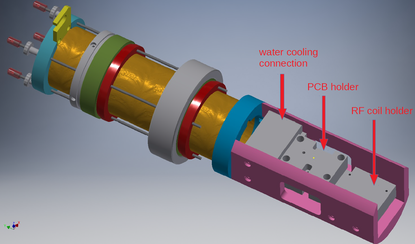
The conductor pattern for magnetic field generation was chosen according to Weiger et al (1) and Williams (2). Biot–Savart calculations were performed to match the geometrical requirements of 1x1x1 mm³ field-of-view (FOV) with a linearity of the gradient fields in each direction deviating at maximum by 5 % from the ideal case. The final design was further validated with finite-element simulations (CST STUDIO SUITE, Computer Simulation Technology GmbH, Darmstadt, Germany). PCBs with 70 µm copper layer thickness were built according to the tailored pattern. For fixation, a complete insert for the MRI system was built (figure 2). The PCBs were glued with a thermal adhesive on aluminum blocks with approximately 3 mm space between the two planes. The aluminum blocks were connected to an aluminum back plane, interfacing the gradient system to a water cooling unit and providing means to attach an RF coil on a holding system. For testing, a 1mm diameter solenoid transmit/receive coil, interfaced to a generic coil interface of the system, was used. All data was acquired on an ultrahigh field small animal MRI system operating at 11.7 T (BioSpec 117/16, Bruker Biospin, Ettlingen, Germany) applying a 2D CTI imaging technique.Results
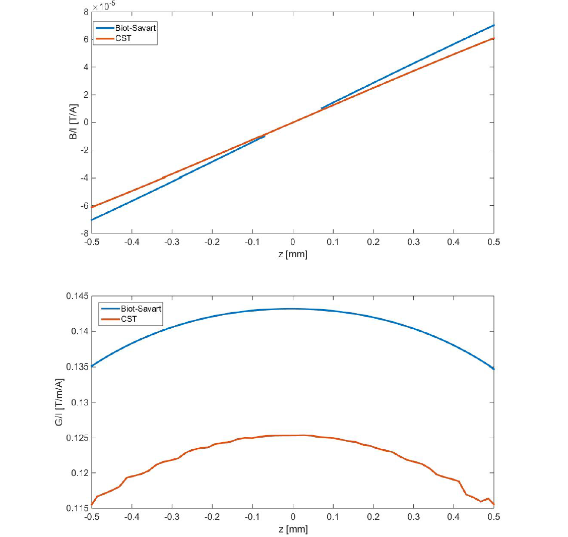
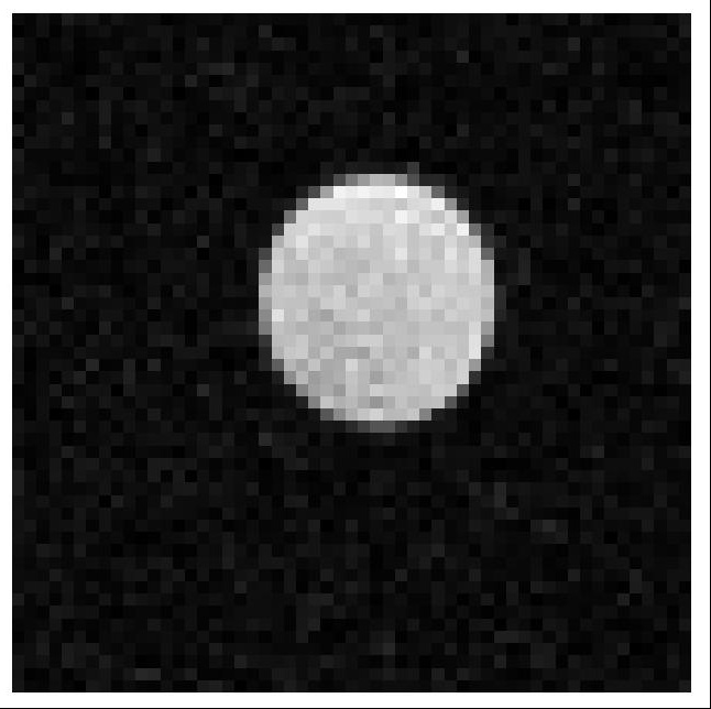
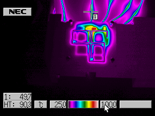
Figure 1 summarizes the Biot–Savart and finite-element (FE) simulations. The FE simulations resemble the shape of the gradient but reveal a slightly reduced amplitude as calculated from Biot-Savart. The MR image of the cross section of a capillary with 800 µm diameter is shown in figure 3. The nearly perfectly round shape of the capillary indicates the excellent linearity of the gradient system. From the apparent dimension of the capillary in the image, the gradient strength was calculated as 0.12±0.02 T/m/A for the x-direction and the y-direction with 0.13±0.02 T/m/A. With the current cooling approach, in continuous operation mode, a gradient strength of 10.3 A could be realized, yielding a peak temperature of about 100 °C at the cable connections interfacing the two parallel PCBs.Discussion
The use of PCBs for constructing efficient micro gradient systems appears feasible. The resulting images indicate excellent performance of the gradients regarding strength and linearity. With the current design, in continuous mode the maximum gradient amplitude is still limited to roughly 1.2 T/m. Considering a duty cycle of roughly 10 % e.g. for a CTI sequence, this simple gradient approach should yield gradient amplitudes in the order of 4 T/m and should be sufficient for most microscopy applications.Conclusion
With the simple PCB-based gradient systems, gradient strengths matching or even outperforming current microscopy systems can be constructed and easily be interfaced to existing small animal MR systems.Acknowledgements
The excellent assistance from the work group ‘Experimental Cardiovascular MRI‘ and the ‘Institute of Microelectronics‘ of Ulm University is gratefully acknowledged.References
1. Weiger, Markus, et al. "NMR microscopy with isotropic resolution of 3.0 μm using dedicated hardware and optimized methods." Concepts in Magnetic Resonance Part B: Magnetic Resonance Engineering 33.2 (2008): 84-93.
2. Williams, G. B., et al. "Design of biplanar gradient coils for magnetic resonance imaging of the human torso and limbs." Magnetic resonance imaging 17.5 (1999): 739-754.
Figures