1759
Magnetic gradient mapping of a 3T MRI scanner using a modular array of novel three-axis Hall sensors1FHNW, University of Applied Sciences and Arts Northwestern Switzerland, Muttenz, Switzerland, 2U947, Inserm, Nancy, France, 3IADI, Université de Lorraine, Nancy, France
Synopsis
This paper presents a multi-point and modular magnetic field sensor system compatible with a 3T-MRI environment. The system features a three-axis magnetometer on a chip. This monolithic sensor is to our knowledge the only integrated sensor commercially available that provides full field vector information as well as sufficient dynamic range and acquisition rate for MRI-applications. We have validated experimentally our demonstrator through the measurement of static magnetic field and magnetic field gradients simultaneously acquired at nine locations within a MRI bore (Prisma, Siemens, Erlangen, Germany).
Introduction
Measuring the magnetic field within an MRI scanner is required in many applications for MRI-instrumentation. ECG signal correction requires measuring the perturbing magnetic field gradients near the ECG electrodes in order to apply correcting signal processing [1]. MR-safety assessment requires a 3D mapping of the magnetic field and its gradient distribution within the MRI bore and in its vicinity [2, 3]. Similarly, the magnetic localization of a surgical tool for interventional MRI can be done by integrating the magnetic gradient measurement within the surgical tool [4]. Besides instrumentation, the mapping of the magnetic field and its gradient is of particular interest for the R&D activities of MRI manufacturers.Purpose
This paper presents a multi-point and modular magnetic field sensor system compatible with a 3T MRI environment, and validates experimentally our demonstrator through the mapping of the static magnetic field and the magnetic field gradients simultaneously acquired at nine locations within the MRI tunnel.Methods
The system features a three-axis magnetometer on a chip (Metrolab Technology SA, Switzerland) [5]. This monolithic sensor is to our knowledge the only integrated sensor commercially available that provides full field vector information as well as sufficient dynamic range and acquisition rate for MRI-applications.
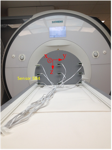
Measurements were performed on a 3T MRI system (Prisma, Siemens, Erlangen, Germany) (Fig. 1). Compared to previous work [6] our system provides a simultaneous multi-point acquisition, which enables faster measurements and the monitoring of non-reproducible effects. It is also important to note that the presented measurements were performed for the first time with a chip that combines on the same die the three-axis sensor element and the processing electronics, which includes a 16-bit analog to digital converter. This level of miniaturization strongly reduces electro-magnetic interferences. The sensor measures both the 3T static magnetic field and the gradients. With 16 effective number of bits, one can detect field changes of approximately 92 µT on top of a 3T base line. This is especially interesting when using the presented three-axis sensor for localization purposes. The static magnetic field allows estimating the sensor orientation, leaving only the sensor position left to be calculated (e.g. by using the unique relationship between the coordinate system of the MRI tunnel and the gradient information).
Results
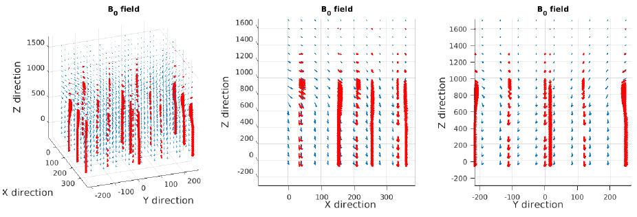
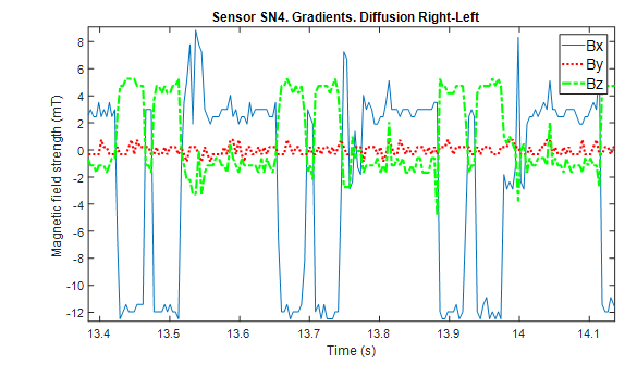
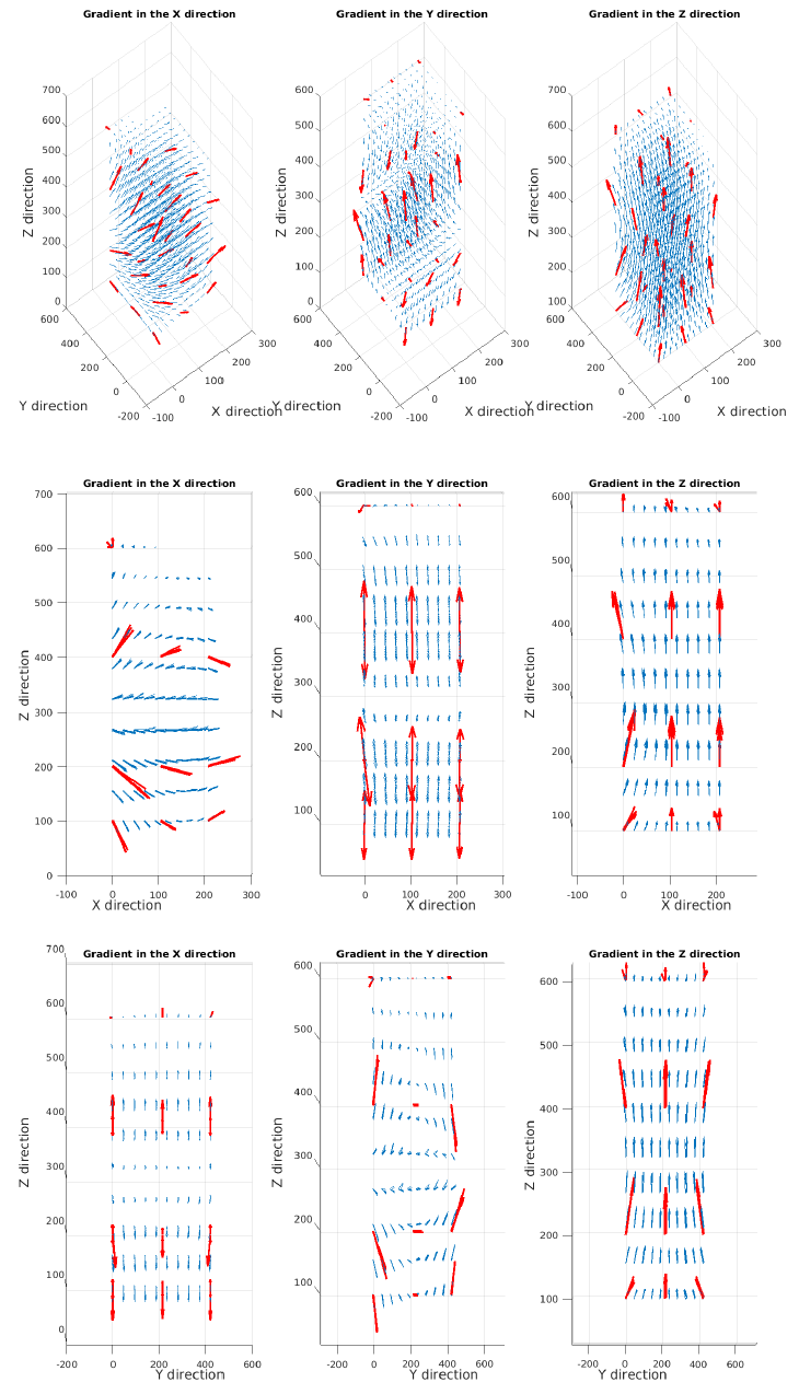
The mapping of the $$$B_0$$$ field is shown in figure 2. It can be seen that, thanks to the mechanical accuracy of the Lego® bricks on which the sensors were mounted, the sensors were perfectly aligned with the MRI axes, since the sensor output is directed along a single axis at the isocenter. Figure 3 displays the transient acquisition of a “diffusion” gradient in the right to left direction. Figure 4 shows the three gradient mappings obtained with our arrangement of nine sensors (Figure 1). After interpolating between the 27 measurement points, we can obtain a more complete mapping. These measurements clearly indicate the vector map induced by a magnetic field gradient, with the Z vector components varying along the gradient directions (around the isocenter –plane $$$Z=0$$$).The system allows also mapping the concomitant fields and illustrates that the vector sum of the $$$B_0$$$ and gradient fields is not perfectly aligned along the bore axis.Discussion
The presented sensor system does not replace a magnetic mapper based on NMR sensors, which provides ppm accuracy to perform tasks such as condition monitoring, maintenance and tuning of gradient systems or characterization of the static field distribution of MRI bores. Noticeable signal alteration in $$$^1H$$$ experiments can be induced by a field error of approximately $$$10^{-9} $$$ Ts, e.g. a field offset of 1µT during 1ms [7]. This is two orders of magnitude lower than the detection level we can achieve with 3D Hall effect sensors integrated in standard CMOS technology like the one we use in this experiment. However, our system allows measuring the full field vector information, which is not accessible through NMR measurements.
The next step is to assess the feasibility of using our system for the characterization of the gradient system. Errors introduced by the gradient amplifiers (such as offset, non-linearity, gain error and delays), and errors induced by eddy currents within the gradient coils, are of particular interest.
Conclusion
By mapping MRI gradient fields, we have experimentally demonstrated that our system is well suited for MRI applications (R&D, safety, or instrumentation). To our knowledge, it is unique in its modularity, its ability to simultaneously acquire several field vectors, and its ability to digitize at high resolution both the static magnetic field and the gradients.Acknowledgements
The authors would like to thank Metrolab Technology SA (Switzerland) for providing technical and financial support.References
[1] Oster, Julien, and Gari D. Clifford. "Acquisition of electrocardiogram signals during magnetic resonance imaging." Physiological Measurement 38.7 (2017): R119.
[2] Ferry, Pauline, Hammen Lucien, Alnnasouri Rada, Felblinger Jacques, and Pasquier Cédric “3D dB/dt measuring bench design and building for safety assessment”. In: International Society for magnetic Resonance in Medicine (ISMRM), 2017 25th Annual Meeting. Abstract 2622.
[3] DELMAS, Antoine, WEBER, Nicolas, PIFFRE, Joris, et al. MRI ‘Exposimetry’: How to analyze, compare and represent worker exposure to static magnetic field ? Radiation Protection Dosimetry, 2017, p. 1-9.
[4] SCHELL, J.-B., KAMMERER, J.-B., HÉBRARD, L., et al. Towards a Hall effect magnetic tracking device for MRI. In: Engineering in Medicine and Biology Society (EMBC), 2013 35th Annual International Conference of the IEEE. IEEE, 2013. p. 2964-2967.
[5] Metrolab Technology SA, MagVector™ MV2 3-axis magnetic sensor, Datasheet, v 2.1 r 1.0 – 07/2016
[6] SCHELL, J., KAMMERER, J., HÉBRARD, L., et al. 3T MRI scanner magnetic gradient mapping using a 3D Hall probe. In: Sensors, 2012 IEEE. IEEE, 2012. p. 1-4.
[7] DE ZANCHE, Nicola,
BARMET, Christoph, NORDMEYER‐MASSNER, Jurek
A., et al. NMR probes for
measuring magnetic fields and field dynamics in MR systems. Magnetic
Resonance in Medicine, 2008, vol. 60, no 1, p. 176-186.
Figures