1756
Driving Mutually Coupled Coils in Gradient Array Systems in Magnetic Resonance Imaging1National Magnetic Resonance Resarch Center (UMRAM), Bilkent University, ANKARA, Turkey, 2Department of Electrical and Electronics Engineering, Bilkent University, ANKARA, Turkey
Synopsis
Gradient array systems recently have gained attention due to their various flexibilities and capabilities in different applications. Reducing the mutual-coupling between the coil elements is one of the constraints during the process of the coil design. However, by determining any existing coupling value between the array elements, required decoupling can be achieved. For a typical trapezoidal gradient current waveform, desired voltage values during rise/fall times, are recalculated considering all mutual-couplings between the array elements. This method is evaluated experimentally for different trapezoidal current combinations and can be used in any gradient array system with mutually coupled elements.
Introduction and Purpose
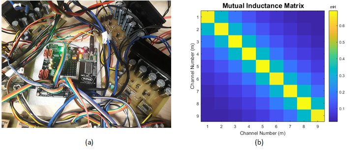
Gradient systems, which are mainly composed of shielded coils and corresponding gradient power amplifier (GPA), are used to spatially encode in each of the x, y and z directions. Gradient array systems recently have gained attention due to their various flexibilities and capabilities in different applications1,2,3. In these systems, there are plurality of coils which are driven by independent GPAs. Although the mutual coupling between the array elements can be reduced by defining a constrain in coil design method1,2, which limits the degree of freedom or even practically impossible to manufacture, residual coupling will be disruptive. However, in gradient system working frequency where loading is not of concern, by using the mutual coupling values between the channels, required compensation can be applied using corresponding independent GPAs to get desired current waveform flowing through each array element. Proposed method is evaluated experimentally for the current values generating different volume of interests (VOIs) with our home-built 9 channel z-gradient array system and 9 GPAs3 (Fig. 1). Overall rise/fall time for each VOI generated by different current combinations is also calculated considering the available current and voltage from the GPAs. Linear gradient fields are applied in z-direction as slice selection and slice refocusing gradients to validate the ability of driving mutually coupled array coils.Methods
For a typical trapezoidal gradient current waveform with determined flat top/bottom values (), required voltage to get the desired rise/fall time (m’th channel), can be achieved using Eq. 1. In this equation Rm and Mm are resistance and self-/mutual-coupling values respectively for N number of channels.
$$V_{p_m} = R_m\cdot I_m +\frac{1}{Δt_m}\sum_{n=1}^{N}M_{mn}\cdot I_n m=1,...,N; Eq.1$$
For effective compensation, we consider the same rise/fall times () for all channels regardless of their current values, which can be found by using Eq. 2, in which, is the available voltage from GPA (VPS = 40V, IPS = 15A).
$$\underset{1 \le m \le N}{\operatorname{max}} \{ \frac{\sum_{n=1}^N M_{mn}\cdot I_n }{V_{PS}-\mid R_m \cdot I_n\mid} \} Eq.2$$
After specifying Δtarray, required voltages for each channel considering mutual-couplings can be achieved for all channels in rising and falling edges of the trapezoidal current waveform where there is coupling between the coils. Measured resistance is about 1.4 Ω for all channels and mutual-inductance matrix is given in Fig. 1.
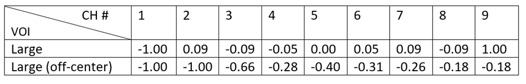
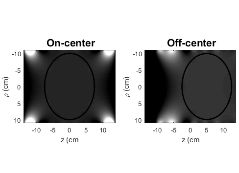
Table 1 contains normalized weightings of the currents in each channel generating two linear gradient fields in on-center and off-center (5 cm shifted) z locations. Both fields has an elliptical homogeneity volume of 20 × 15 cm in radius and length respectively. Magnetic field profiles of the on-center and off-center volumes in simulation are demonstrated in Fig.2 by applying current values in Table 1.
Results
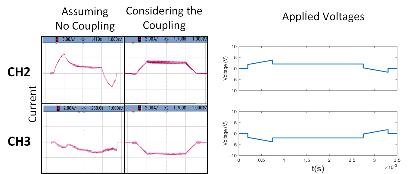
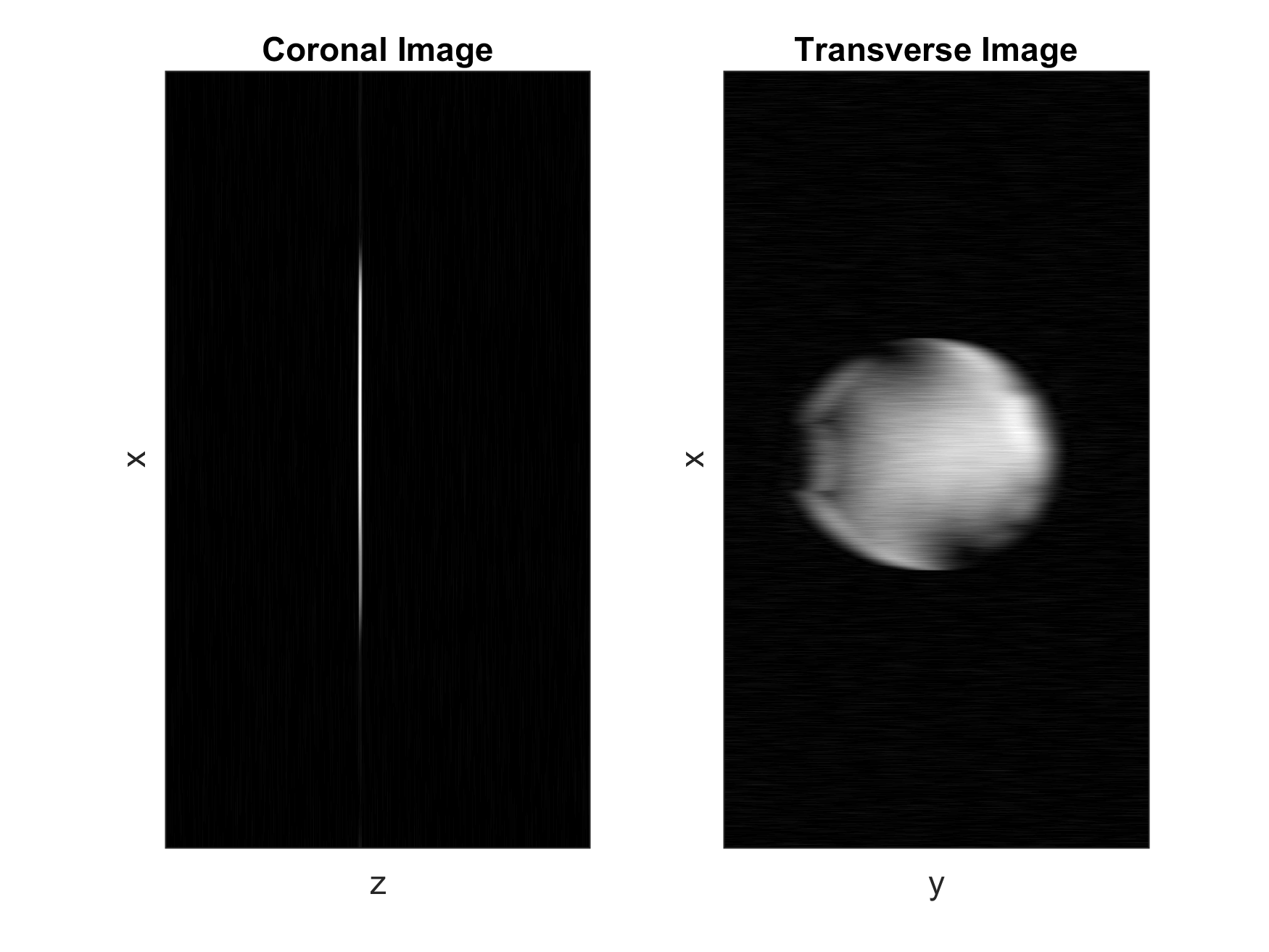
Rise/fall times are calculated and rounded to be 550 µs, 800 µs and 1100 µs for large, small and off-center VOIs respectively. Measured current waveforms for 2 channels along with applied voltage considering mutual-coupling between the channels given in Fig. 3. In Fig. 4, on-center z-gradients are applied in a slice selection problem as slice selection and slice refocusing gradients which has both positive and negative polarity of currents. Fig.4 validates the excited slice in both coronal and transverse planes.Discussion and Conclusion
In this work, effective active decoupling for gradient array systems for typical trapezoidal current waveforms with same rise/fall times between arrays is proposed. Similar approaches also can be used for different current waveforms and gradient array systems with certain inductive coupling between their elements. Although the slew-rate for each channel can be different, but effective slew-rate of the system can be determined using calculated rise/fall times of the array and generated total gradient strength. Since the total required voltage in the array system remains constant before and after compensation, no additional sources in terms of GPA capabilities are needed. After initial determination of the load characteristics, this method can be dynamically applied during the sequences. In conclusion, active decoupling can also be applied in gradient array systems which almost independent of loading with no cost and can potentially improve coil performance by relaxing the coupling constraints.Acknowledgements
Authors thank to Toygan Kilic and Cemre Ariyurek.References
1.Smith, E., Freschi, F., Repetto, M., & Crozier, S. (2017). The coil array method for creating a dynamic imaging volume. Magnetic resonance in medicine, 78(2), 784-793.
2.Littin, S., Jia, F., Layton, K. J., Kroboth, S., Yu, H., Hennig, J., & Zaitsev, M. (2017). Development and implementation of an 84‐channel matrix gradient coil. Magnetic Resonance in Medicine.
3. K. Ertan, S.Taraghinia, A. Sadeghi, E. Atalar “A z-gradient array for spatially oscillating magnetic fields in multi-slice excitation” Magn Reson Mater Phy (2016) 29: 1. doi:10.1007/s10334-016-0568-x, Abstract No:81
4.Taraghinia, S., Ertan, K., Yardim, A.B. and Atalar, E., Efficient Ripple Current Reduction in Gradient Array System Using Optimized Phase Control Signals with One Stage LC Filter, ESMRMB, Barcelona, Spain, 2017
Figures