1754
Comparison of patient bore tube supporting structures for a high-performance gradient whole-body MRI system to reduce acoustic noise1Yokohama Development Center, Toshiba Medical Systems, Yokohama, Japan
Synopsis
A whole-body MRI scanner with high-performance gradient system produces loud acoustic noise during scan. In the present study we have evaluated the acoustic noise performance for a new gantry structure aimed at noise reduction with a vacuum chamber insert between the gradient coil cylinder and the patient bore tube cylinder. Two different supporting structures for the bore tube were compared. The method supporting the bore tube by means of a beam structure mounted on the feet of magnet scored better performance than the alternative method supporting it by short brackets mounted at the edges of magnet bore opening.
INTRODUCTION
Gradient coils in MRI systems are subject to Lorentz-force-induced mechanical vibrations due to the rapidly varying electric current, causing noise and resulting in patient’s discomfort. A novel acoustic noise reduction technique for whole-body MRI systems was previously described.1,2 This technique drastically reduces both airborne and through-solid vibration propagation introducing a vacuum chamber and by supporting the gradient coil independently from the rest of magnet gantry structure. This technique is effective independently of the imaging sequence.3 More recently research-oriented high-performance gradient systems have been developed with Gmax ≥100mT/m.4 In order to make such systems suitable for daily clinical use, additional noise reduction strategies are required to ensure patient comfort. In the present work we compare two different patient bore tube (bore tube) supporting structures, and investigate a low acoustic noise gantry structure with a vacuum chamber, suitable for high-performance whole body MRI systems.METHODS
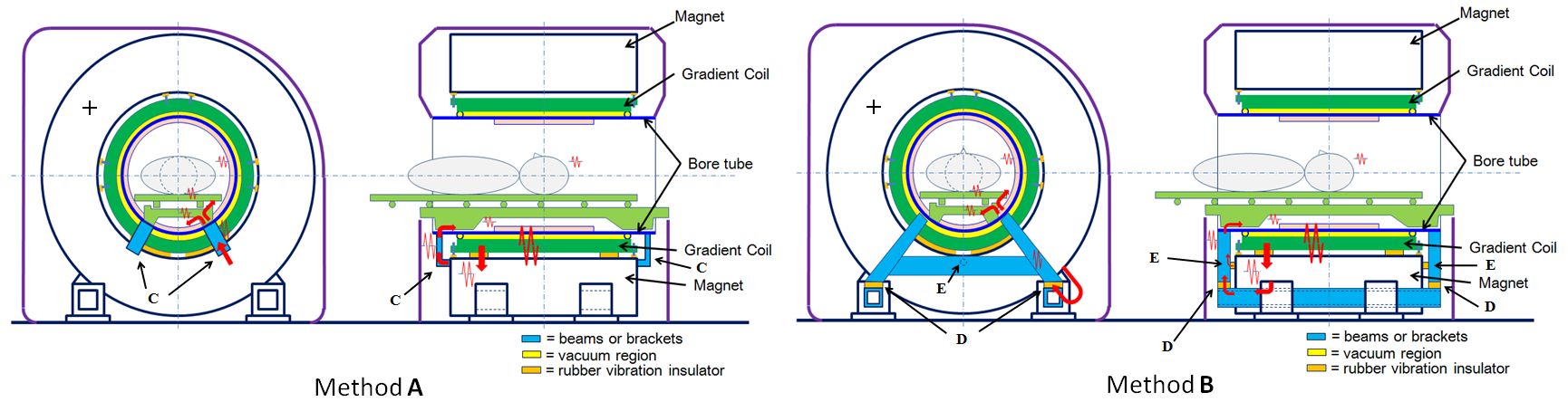
In method A (Figure 1, left), the bore tube is supported using short brackets, in blue, mounted rigidly to the magnet near the front/rear edges of the bore opening (C). In method B (Figure 1, right), the tube is supported using a beam structure, in blue, mounted to the feet of magnet. Rubber vibration insulators are inserted between the vertical beams and the horizontal beams mounted at the feet of the magnet (D). Additional bushing-type rubber insulators are inserted between the magnet and the vertical beams to limit the motion of the beam structure in the direction of the static magnet field (E). The rest of the structure is identical for both methods. The gradient coil is mounted onto the inner bore of the magnet using rubber insulators. The spacing between gradient coil and bore tube, within the gradient coil, forms a sealed cylindrical volume, in yellow. To reduce the airborne propagation of noise, the air pressure within this volume was reduced to less than 5kPa using a vacuum pump. A 3T MRI system (Gmax: 100mT/m, SR: 200mT/m/ms, patient bore diameter: 60cm) was used for the evaluation. The following instruments were used for measurement and analysis: FFT Analyzer: OROS corp. OR38, Impact Hammer: PCB Piezotronics Corp. 352C65, Acceleration pickup: Piezotronics Corp 086D20, Acoustic noise measurement: RION Corp. NA-28.
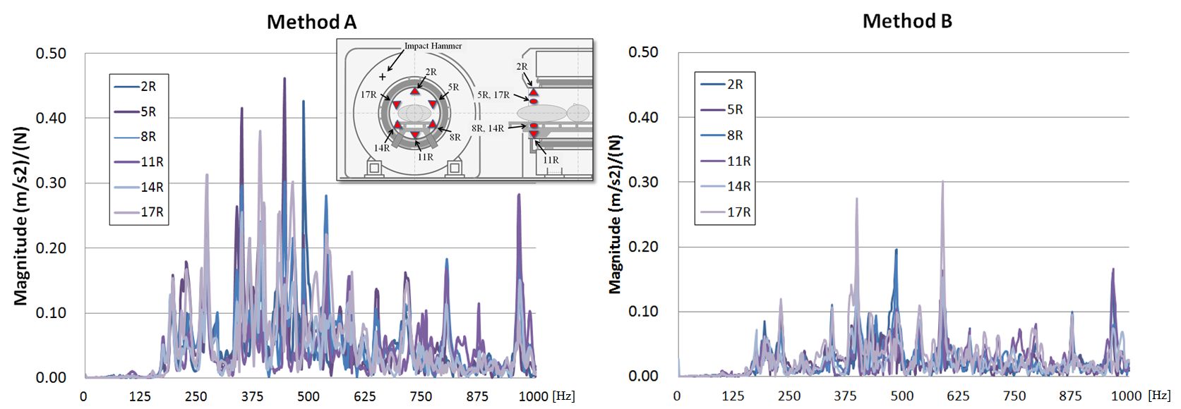
TEST-1): The vibration transmission property from magnet to bore tube was evaluated by measuring the transfer function using the impact hammer. The location of impact is indicated by the “+” in Figure 1. Acceleration pickups were attached to the bore tube in 18 points.
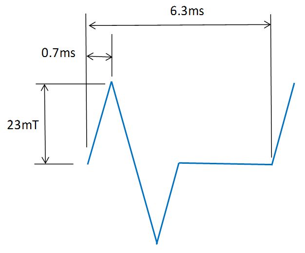
TEST-2): Measurements were performed using three different gradient waveforms: SEQ-1): Series of triangular bipolar waveforms (Figure 2), applied to all three channels simultaneously; SEQ-2): SE-EPI DWI with b=1000s/mm2, TR/ TEeff =4000/100ms, FOV(ro,pe)=23.0x6.8cm, Slice Thickness=2mm, MX(ro,pe)=1442, NS=16, Echo space=0.9ms; SEQ-3): 2D SSFP with TR/TE=4.2/2.1ms, FOV(ro,pe)=31x30cm, Slice Thickness=7mm, MX=2562, NS=16, bandwidth=250kHz.
Two measurements were performed for both
methods:
TEST-2)-a: Acceleration measurement at 6
points on the bore tube using SEQ-1);
TEST-2)-b: Weighted sound pressure level
(acoustic noise level) measurement for 10s using all three sequences at 14
points within the bore tube, per IEC60601-2-33 (Figure 5). The microphone was
placed onto the couch table, where a patient’s ear is supposed to be located.
By moving the couch table, 14 data point for both ears were measured from z= -600mm
to +600mm with 200mm interval.
RESULTS AND DISCUSSION
TEST-1): Figure 3 displays the results for the transfer function on the 6 points. The magnitude of the transfer function for the two methods changes depending on the measuring point and frequency. The average magnitude between 0-1000Hz at the 6 points for method B was 50% smaller compared to method A: 0.0240(B) vs. 0.0480(A) m/s2/N. The average magnitude at all 18 points for method B at all 18 points was 44.7% smaller compared to method A: 0.0232(B) vs. 0.0419(A) m/s2/N.
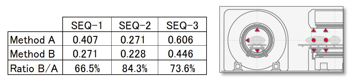
TEST-2)-a: Figure 4 shows the results of acceleration measurement using the three gradient waveforms. Measuring points are shown in the Figure. Average of acceleration on method B is about 25% smaller compared to method A.
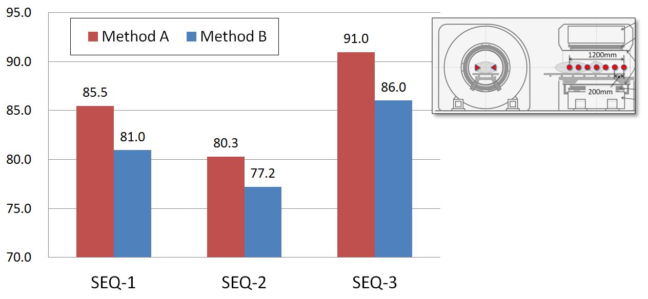
TEST-2)-b: Figure 5 shows the results for the acoustic noise level measurement for all gradient waveforms. The average acoustic noise level across all sequences on both methods was 85.6(A) and 81.4(B) dBA respectively. The acoustic noise level measured with method B was 4.2dBA smaller compared to method A.
CONCLUSION
For a high-performance gradient whole body MRI system using vacuum chamber, the method supporting the bore tube by means of a beam structure demonstrated better acoustic noise performance than the alternative method utilizing short brackets mounted at the edges of magnet bore opening.Acknowledgements
No acknowledgement found.References
1. Katsunuma A, Takamori H, et al. , “Silent MRI system” by interrupting the vibrational transmission through the air and solid structures, Proc. of ISMRM 2000, No.1372.
2. Katsunuma A, Takamori H, Sakakura Y, Hamamura Y, Ogo Y, Katayama R. Quiet MRI with novel acoustic noise reduction. MAGMA. 2002 Jan;13(3):139-44. PubMed PMID:11755088
3. Price D. L., Wilde J.P., et.al., Acoustic Noise on 1.5T MRI Systems: Worst Case and Comparative Measurements, Proc. of ISMRM 2001, No.1763.
4. Kimmlingen R, Eberlein E, Dietz P, et.al., Concept and realization of high strength gradients for the Human Connectome Project, Proc. of ISMRM 2012, No.696.
Figures