1751
High-performance of Multi-axes DWI sequences using Advanced Charge of Gradient power supply1MRI Systems Development Department, Toshiba Medical Systems Corporation, Tochigi, Japan
Synopsis
Optimizing the energy distribution to the 3 axes output sections of the gradient power supply allows attaining high-performance Multi-axes DWI sequences. In this study, we propose an ‘Advanced Charge’ method for preferential energy supply with one axis emitting the largest fraction of output energy of all 3 axes. To realize it, the energy consumption simulation model for gradient power supply and gradient coil was updated accounting for the energy distribution to each individual axis. The new simulation model was implemented in the Advanced Charge control and the feasibility of high-performance of Multi-axes DWI sequences was then confirmed.
Introduction
Accurate estimation of the energy consumption for gradient power supply and gradient coil enables the optimization of the acquisition scheme. Consequently, a well-built simulation model allows for high-performance DWI sequences [1].
The gradient power supply controls the energy distribution to the 3 axes output sections, without the supervision of the MRI system controller. Its performance is measured by its stability and robust operation as a power supply, not always reflected in an equally robust energy distribution to each gradient coil axis. Therefore optimizing the energy distribution to all 3 axes is a requirement for high-performance Multi-axes DWI sequences.
We propose an ‘Advanced Charge’ method for preferential energy supply with one axis emitting the largest fraction of output energy of all 3 axes. To realize it, the energy consumption simulation model for gradient power supply and gradient coil was updated accounting for the energy distribution to each individual axis. The new model was implemented in the Advanced Charge control and the feasibility of high-performance of Multi-axes DWI sequences was tested.
Materials and Methods
1) Energy consumption simulation model.
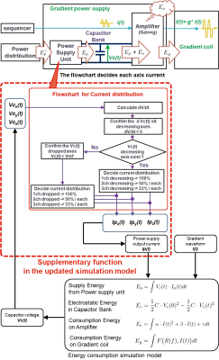
Figure 1 depicts the gradient power supply and gradient coil and the corresponding simulation model. Their energy consumption depends on the current, I(t), output by the gradient power supply, included in the simulation model. The internal energy variation of the gradient power supply, in turn, was set to be the simulation output. The capacitor bank voltage Vc(t) was adopted as an indicator of internal energy. The conventional model accounts for single axis power consumption; however in the updated model the power supply output current Ip(t) (Ipx(t),Ipy(t),Ipz(t)) distribution is determined by the capacitor bank voltage value on all 3 axes, Vc(t) (Vcx(t),Vcy(t),Vcz(t)).
2) Impact of the Advanced Charge on Multi-axes DWI sequences.
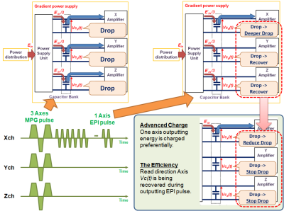
Figure 2 plots the Vc(t) (Vcx(t),Vcy(t),Vcz(t)) transition during the acquisition of a Multi-Axes DWI sequence. While outputting MPG pulses, all axes Vc(t) drop and the internal power supply charges all axes capacitor banks. The same happens when EPI pulses are outputted, with all capacitor banks being charged. Consequently, the Vc(t) of the axis outputting the EPI pulses experiences a deeper drop. By introducing the Advanced charge, the Vc(t) drop of the axis outputting the EPI pulses is significantly reduced.
3) Updated simulation model.
The supplementary function in the updated simulation model is depicted in Figure 1. The internal power supply output current Ip(t) (Ipx(t),Ipy(t),Ipz(t)) is an input to the simulation model, and its distribution across each axis is updated based on values of Vc(t), as depicted in the flowchart. The updated Ip(t) and gradient power supply output current I(t) are used as input signals, and each axis Vc(t) is calculated by the simulation model. The procedure is iterated, reproducing the dynamic variation of Vc(t).
In the case of the Advanced Charge, each axis Ip(t) is updated according to the time variation of Vc(t) (dVc(t)/dt). When dVc(t)/dt is negative for either axis, the corresponding axis is considered to be outputting gradient magnetic field. Ip(t) is preferentially distributed to such axes, and only axes outputting gradient magnetic field are charged.
4) Evaluate the efficiency of Advanced Charge.
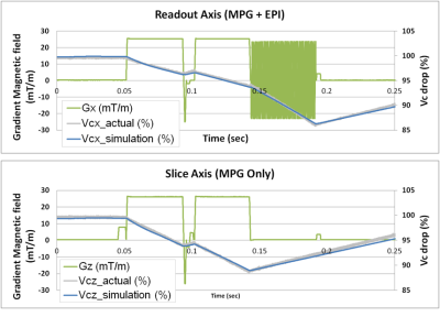
a) Each axis Vc(t) (Vcx(t),Vcy(t),Vcz(t)) dynamic variation during the acquisition of Multi-Axes DWI sequences was confirmed on the updated simulation model, and the simulated Vc(t) was compared to the actual Vc(t).
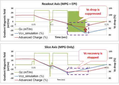
b) The simulated Vc(t) on the conventional control was compared with the Advanced Charge control. DWI b-value and TE were varied to evaluate their range of flexibility on the Advanced Charge control.
Results and Discussion
a) Using the optimized model, each axis Vc(t) can be calculated dynamically at a 50ms sampling rate while acquiring a Multi-Axes DWI sequence. The error for the model was measured to be within 5% (Fig. 3).
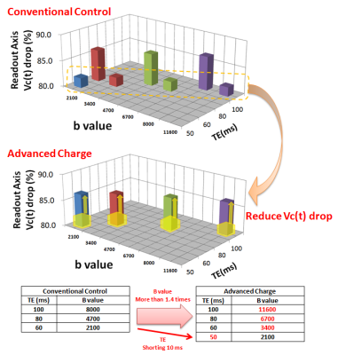
b) Vc(t) was evaluated using DWIs at various b-values and TEs with matrix=128x128, FOV=25x26cm and ETS=0.65ms. In these scan conditions, the Vc(t) drop for the readout axis was improved to the excess of 5% on Advanced Charge control (Fig. 4). The added flexibility for Multi-Axes DWI sequences allows to shorten the TE by 10 ms and to raise the b-value more than 1.4 times at the same TE (Fig. 5).
Conclusion
The energy consumption simulation model was updated to more efficiently distribute internal energy to each axis. As the result, the model error was measured to be within 5% while acquiring Multi-Axes DWI sequences. Furthermore, by implementing the Advanced Charge control in the model, Multi-Axes DWI sequences allow for increased flexibility, shortening the TE and raising the b value at the same TE.Acknowledgements
No acknowledgement found.References
[1]Sho Kawajiri et al., In proc ISMRM 24(2016) 3642Figures
