1750
An actively-shielded planar gradient coil design scheme in limited coil-layer-placing space1South China University of Technology, Guangzhou, China, 2The University of Queensland, Brisbane, Australia
Synopsis
A novel gradient coil design scheme was proposed for use in planar MRI systems. Unlike conventional scheme in a limited magnet pole-pole space which usually applies unshielded design, the novel strategy integrated a set of actively-shielded gradient coils in only four layers in the pole-pole space with the utilization of the system peripheral sections. The design largely improved the shielding effect of the gradient coils and meanwhile left adequate space for the patients and installation of cooling device. The design scheme did not significantly increase the system manufacturing complexity either.
Introduction
For planar MRI system, owing to the space limits, it is difficult to insert both primary and shielding coil layers onto the magnet pole. An enlargement of the pole-pole distance will exponentially increase the manufacture cost of the permanent magnet. In MRI engineering practice, unshielded or partially shielded gradient coils are used [1-2], introducing large eddy current with surrounding metal structures, which affects the magnet stability and interferes the imaging quality [3]. Besides, the induced eddy current is also potential to generate large acoustic noise [4-5]. In this abstract, an inverse boundary element method (BEM) [6] was applied to design a set of unconventional, actively-shielded gradient coils for use in a planar MRI system.Methods
In a BEM-based gradient coil design procedure, the following optimization problem can be formed$$ ({\bf{A^TA}}+{\it{w}}_1{\bf{B^TB}}+{\it{w}}_2{\bf{L}}+{\it{w}}_3{\bf{R}}){\bf{X}}={\bf{A^TT_{Bz}}}\qquad\qquad(1)$$where A is the system matrix relates the coil current density and magnetic fields over the diameter of spherical volume (DSV), B is the matrix relates to the coil current density and magnetic fields over the shielding region, L is the inductance matrix, R is the resistance matrix, X is stream function vector, TBz is the target gradient magnetic field, w1, w2 and w3 are weighting factors. As equation (1) is ill-conditioned, the least square method (LSM) was used here to find the optimized solution. The optimization process was under the following constraints$$\begin{cases}{\bf{AX}}<\varepsilon\cdot{\rm{max}}(|{\bf{T_{Bz}}}|)+{\bf{\rm{T}}_{Bz}}\\-{\bf{AX}}<\varepsilon\cdot{\rm{max}}(|{\bf{T_{Bz}}}|)-{\bf{\rm{T}}_{Bz}}\end{cases}{\qquad\qquad}(2)$$$$\begin{cases}{\bf{BX}}<s_{\rm{Bz}}\\-{\bf{BX}}<s_{\rm{Bz}}\end{cases}{\qquad\qquad}(3)$$where ε is the maximum target field error and sBz is the maximum stray field intensity.
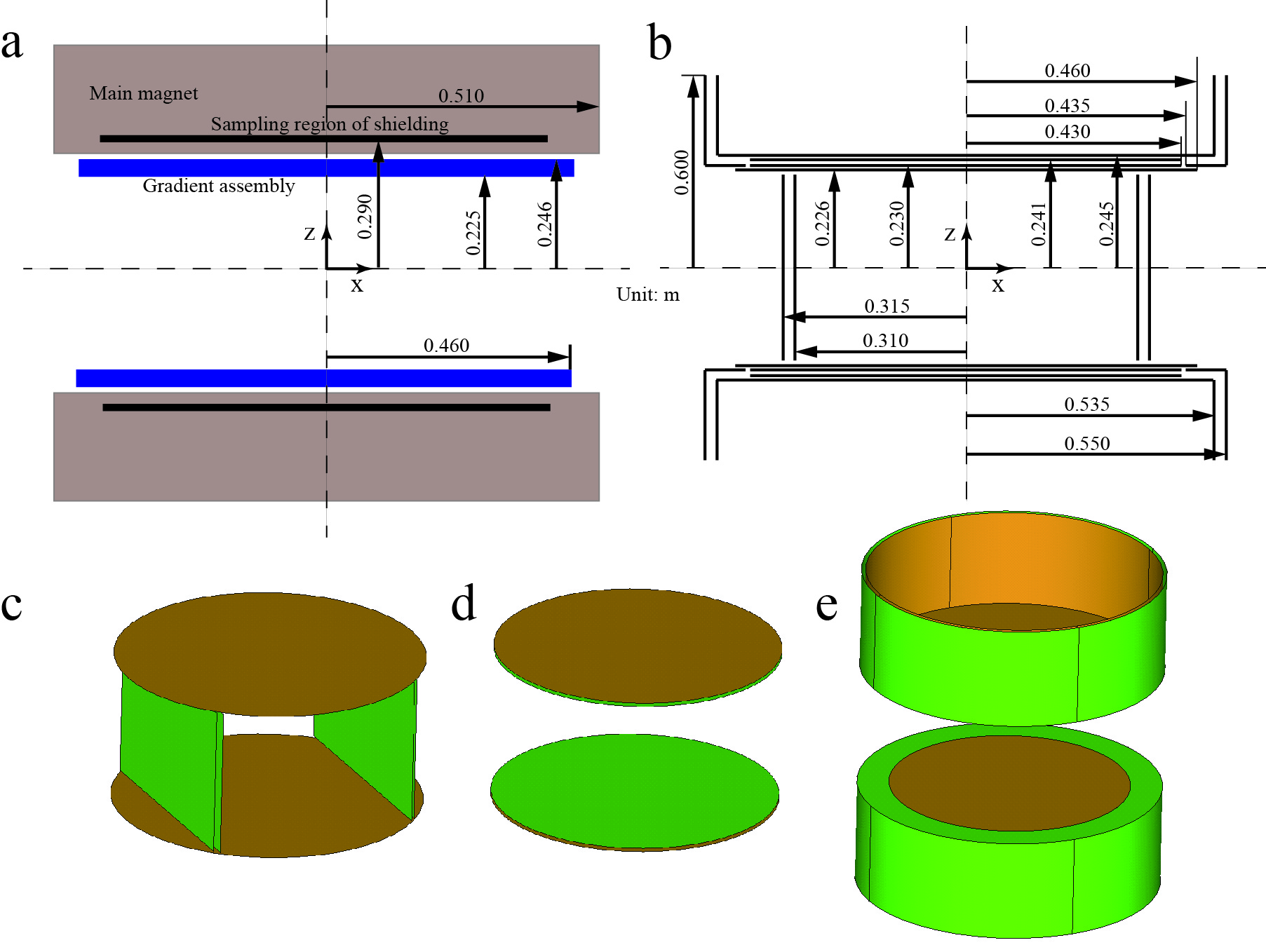
Fig. 1(a) illustrates a planar MRI system, with a profile of the gradient assembly and main magnet. The coil layers and dimensions of the proposed actively-shielded planar gradient coil design concept are given in Fig. 1(b). In the limited magnet-pole space, there are only four coil layers placed, and the rest of the coils are placed in the peripheral section of the system, as shown in the 3D configuration (see Fig.1(c)~(e)) for the x, y and z coils, respectively.
In the design process, the maximum target field error was set as 5% for all the coils, the weighting factor w1, w2 and w3 are 1, 0.2 and 0.5, and the maximum stray field intensity was set as 5 Gauss, 5 Gauss and 12 Gauss (the achievable mimimum stray field constraint based on many trials) for the x, y and z coil respectively. The DSV is 40 cm.
Results
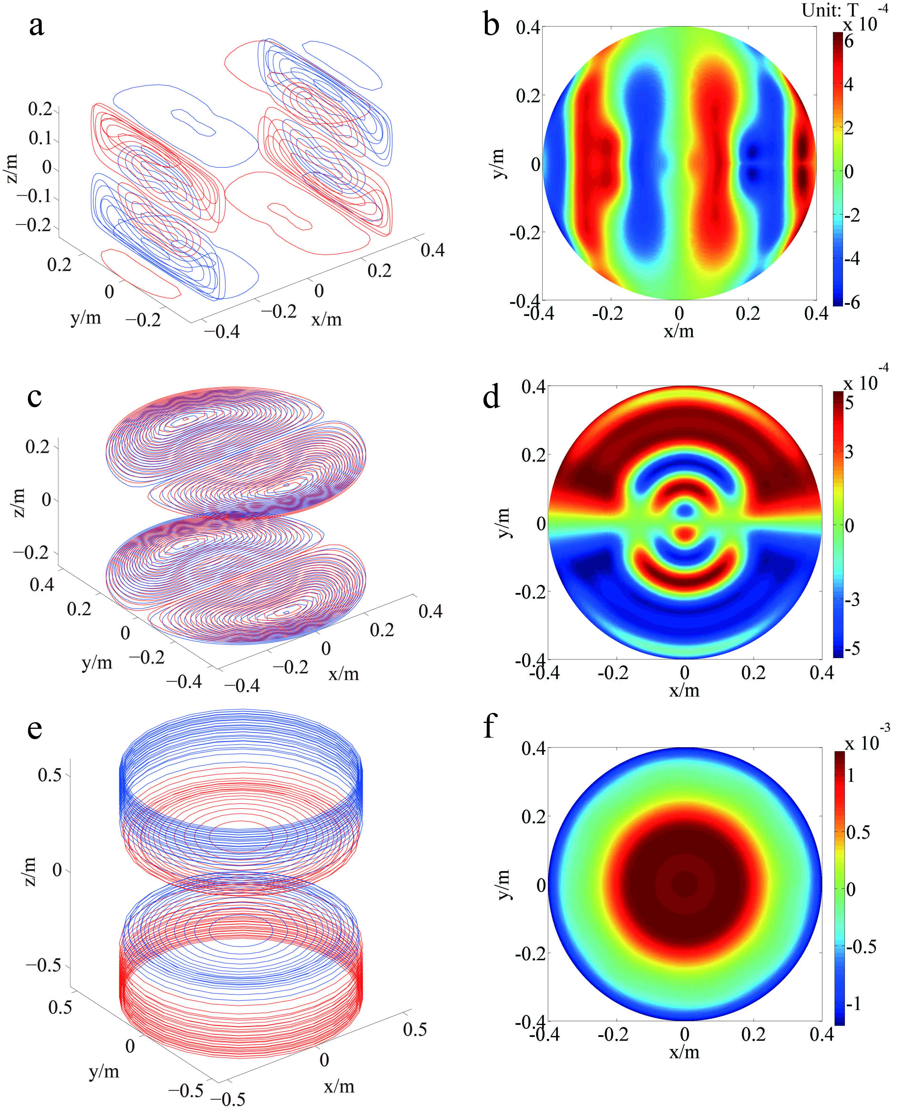
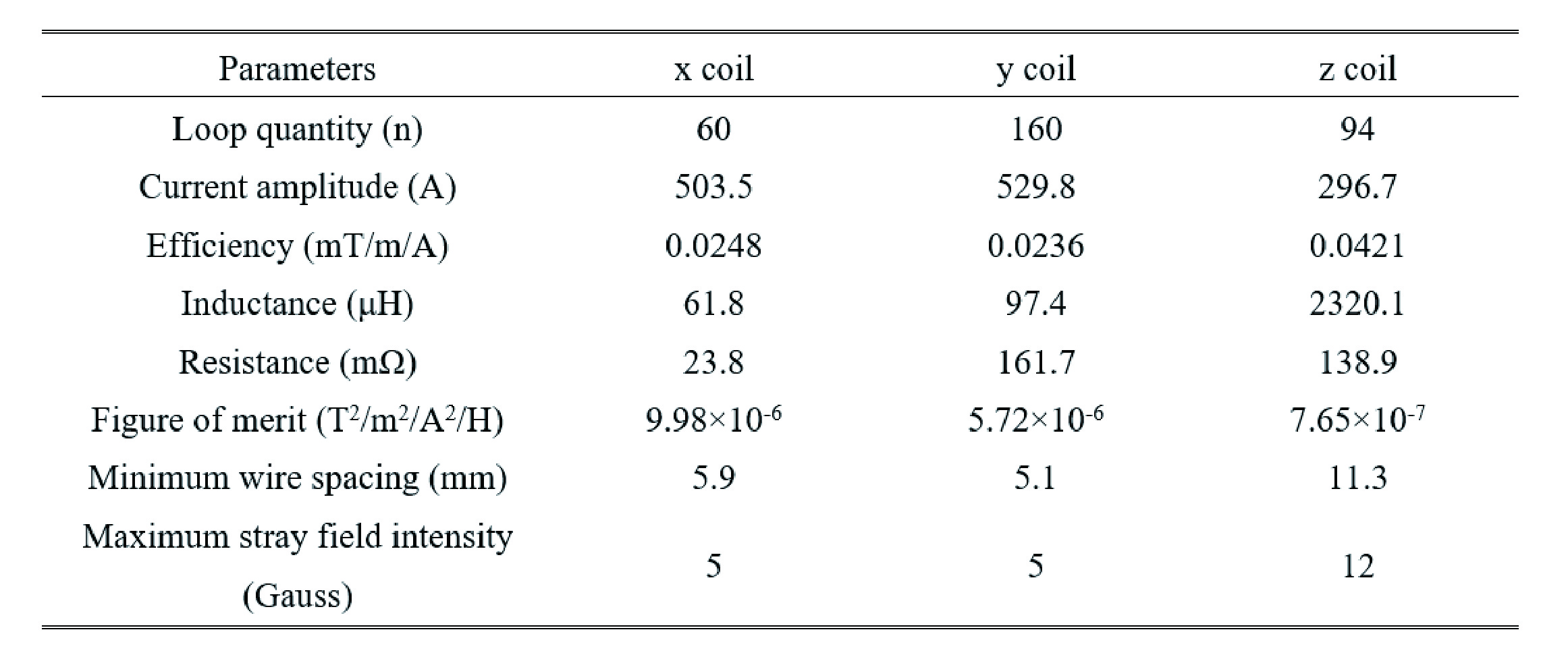
The designed three sets of gradient coils were illustrated in Fig. 2 (a), Fig. 2(c), Fig. 2(e) and their stray field distributions on the samping region of shielding were displayed in Fig. 2(b), Fig. 2(d) and Fig. 2(f). The contour colors in the coil patterns indicate current directions. The coil performance parameters were listed in Table I. By comparing to the conventional unshielded coil designs with identical/approximate dimensions (not shown here), the maximum stray field intensity was reduced from 61 Gauss to 5 Gauss for the x coil, 67 Gauss to 5 Gauss for the y coil and 30 Gauss to 12 Gauss for the z coil.Conclusion
In this work, we propsed a novel gradient coil designs for planar MRI systems. The design has several advanrages: (1) the design has no significant increase in system fabricating complexity. (2) The proposed novel actively-shielded gradient coil design scheme has only four coil layers in the magnet-pole direction, which is practical to use in tyipcal planar MRI system. (3) This method largely improved the coils’ shielding performance compred to conventional unshielded design.Acknowledgements
This study was supported by the National Key Research and Development Program of China (No. 2016YFC0100800, 2016YFC0100801), National Natural Science Foundation of China (No. 61528102, 61671229), Science and Technology Program of Guangdong, China (No. 2015B020214006, 2016A050502026), Guangdong Natural Science Foundation (No. 2015A030313234), Science and Technology Program of Shanghai, China (No. 15441907500).References
[1] M. Zhu, L. Xia, F. Liu, and S. Crozier, "Deformation-space method for the design of biplanar transverse gradient coils in open MRI systems," IEEE Transactions on Magnetics, vol. 44, pp. 2035-2041, 2008. [2] G. Shou, L. Xia, F. Liu, M. Zhu, Y. Li, and S. Crozier, "MRI coil design using boundary-element method with regularization technique: A numerical calculation study," IEEE Transactions on Magnetics, vol. 46, pp. 1052-1059, 2010. [3] F. Liu and S. Crozier, "An FDTD model for calculation of gradient-induced eddy currents in MRI system," IEEE Transactions on Applied Superconductivity, vol. 14, pp. 1983-1989, 2004. [4] W. A. Edelstein, R. A. Hedeen, R. P. Mallozzi, S. A. El-Hamamsy, R. A. Ackermann, and T. J. Havens, "Making MRI quieter," Magn Reson Imaging, vol. 20, pp. 155-63, 2002. [5] Y. Wang, F. Liu, X. Zhou, Y. Li, and S. Crozier, "A numerical study of the acoustic radiation due to eddy current-cryostat interactions," Medical Physics, vol. 44, pp. 2196-2206, 2017. [6] C. Cobos Sanchez, "Forward and inverse analysis of electromagnetic fields for MRI using computational techniques," University of Nottingham, 2008.Figures