1747
An 8 Channel Dipole Transmit Array and 8 Channel Loop Receive Array for Head Imaging of Non-Human Primates at 10.5T1Center for Magnetic Resonance Research, University of Minnesota, Minneapolis, MN, United States
Synopsis
Described herein is the design, construction, and testing of a head coil for imaging non-human primates at 10.5T. The coil is composed of an 8-channel decoupled dipole array for transmit and an 8-channel loop array for receive. We present preliminary transmit efficiency, SNR, noise correlation, and g-factor results for a phantom with immediate plans to acquire in vivo images. This coil is a proof of concept for higher channel count receive arrays of 16 or 24 loops for head imaging of non-human primates at 10.5T.
Introduction
Previous work [1] describes the development of a 16 channel TEM transmitter with 6 channel loop receiver for imaging the brain of non-human primates at 7T. This design proved successful due to the SNR benefits of a close-fitting loop receive array in combination with a transmit array that uses line (TEM) elements which benefit by being inherently decoupled from the loop elements in the receive array.
There are several benefits to using dipole elements at high field which have been demonstrated at 7T and 10.5T [2]. Other work has demonstrated the advantages of a loop-dipole combination [3].
In this work, we develop a non-human primate head coil at 10.5T which uses an 8-channel dipole array for transmit with an 8-channel loop array for receive. This design is a first step towards development of an 8-channel dipole transceive with a 16 or 24-channel loop array for receive.
Methods
Dipole Optimization
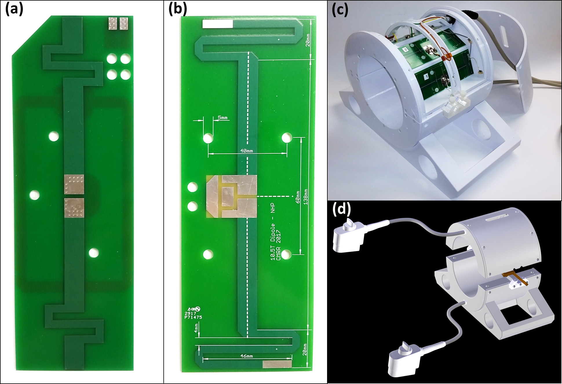
The fractionated dipole developed for [4] was chosen as the basis for this 8-channel transmit array. Because the self-resonant frequency of this dipole is 590 MHz (figure 1a), which is much higher than 447 MHz (the proton Larmor frequency at 10.5T), the dimensions of the meander structures on this dipole were parameterized and simulated in XFdtd 7.5 (Remcom, USA). The resultant structure, determined via simulations and verified experimentally, is self-resonant at 447 MHz (figure 1b).
Transmit Array
A clamshell enclosure with dimensions of 28 cm outer diameter, 18 cm inner diameter, and 22 cm length (figure 1c) was fabricated in-house from white PETG using an F400 (Fusion3, USA) 3D printer. Four dipoles are housed in the upper assembly and another four in the lower assembly (figure 1d). The input impedance of the loaded dipole falls very close to 50 ohms and thus the feed point consists of nothing more than a 1:1 lattice balun. Due to the proximity of neighboring elements and the relatively light load being imaged, it is necessary to decouple nearest neighbors using decoupling circuits located between both ends of neighboring dipoles. This dipole decoupling method was described previously by Connell et al. [5].
Receive Array
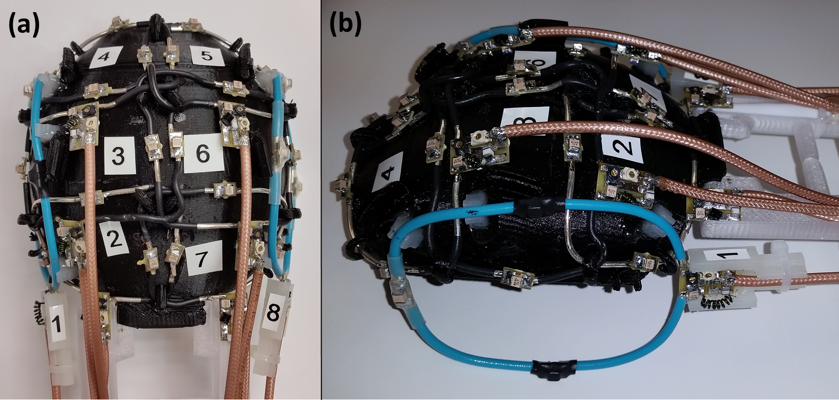
The receive array is composed of eight actively detuned loops. Six loops are mounted on a 3D printed head cap (figure 2a) and two ear loops snap onto the head cap via a set of nylon hooks (figure 2b). Loops are connected via 3λ/4 length coaxial cables to an 8-channel receive box (Virtumed, USA) which houses low noise, low input impedance preamplifiers (WMA447A, WanTcom, USA).
MRI System
All phantom data was acquired on a Siemens MAGNETOM 10.5T MRI system. B1+ maps were acquired using an AFI sequence [6]. The intrinsic SNR was calculated from a noise scan (which was also used to calculate the noise correlation matrix) and a gradient echo image [7] which was corrected to simulate 90° excitation using the acquired B1+ map. All images were acquired using transmit phases set for CP-mode excitation.
Results
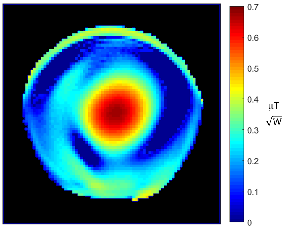
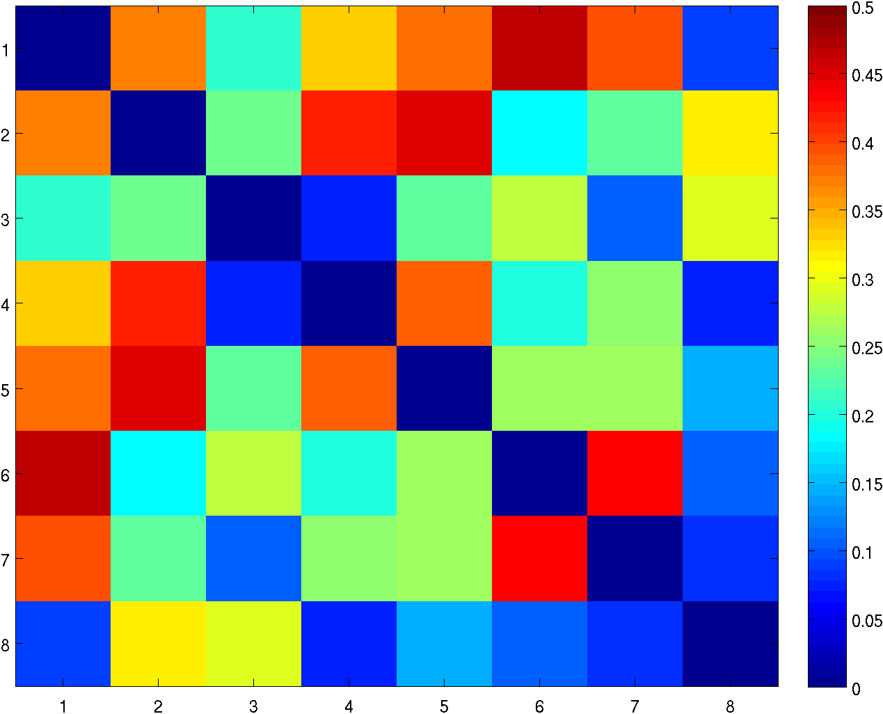
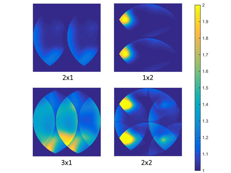
While in vivo images have not yet been acquired, the coil has been used successfully to acquire data on a 10 cm diameter spherical phantom. At the center of the sample the peak transmit efficiency is 0.66 µT/√W (figure 3) and the intrinsic SNR is 570 /µL. The noise correlation matrix for the receive array is shown in figure 4 and a g-factor map is shown in figure 5.Discussion
While the necessity to decouple neighboring dipoles increases the complexity of the transmit array, dipole elements have minimal interaction with the loop receive array, making detuning the transmit array during reception unnecessary. This will enable us to use the transmit array as a transceiver array, thus boosting our total number of receive channels to 16. This will improve both SNR and g-factors.
Further work is needed to improve upon these preliminary results. Noise correlation is poor, despite efforts to geometrically and preamp decouple the receive array. Furthermore, g-factor maps suggest a problem with one of the loops in the receive array.
Conclusion and Future Work
With respect to RF hardware development, this work details the first small but important step towards high resolution brain imaging at 10.5T. Described herein is a proof of concept for a decoupled dipole transmit array and loop receive array combination for imaging non-human primates at 10.5T.
In the short term, we intend to present in vivo images using the coil as described. Longer term goals include expanding the receive array to 16 or 24 loops and converting the transmit-only array to a tranceive array thus expanding the number of available receivers by an additional 8 channels.
Acknowledgements
This research was funded by the following NIH grants: P41 EB015894, P30 NS076408, S10 RR029672, and U01 EB025144.References
[1] Adriany G, Harel N, Yacoub E, Moeller S, Ghose J, Ugurbil K. A 21 Channel Transceiver Array for Non-Human Primate Applications at 7 Tesla. Proc Intl Soc Mag Reson Med 2010; 18: p. 1490.
[2] Wiggins GC, Zhang B, Lattanzi R,Chen G, Sodickson D. The Electric Dipole Array: An Attempt to Match the Ideal Current Pattern for Central SNR at 7 Tesla. Proc Intl Soc Mag Reson Med 2012; 20: p. 541.
[3] Eryaman Y, Guerin B, Kosior R, Adalsteinsson E, Wald LL. Combined loop + dipole arrays for 7 T brain imaging. Proc Intl Soc Mag Reson Med 2013; 21: p. 393.
[4] Woo MK, Lagore RL, DelaBarre L, Lee B-Y, Eryaman Y, Radder J, Erturk A, Metzger G, van de Moortele P-F, Ugurbil K, Adriany G. A Geometrically Adjustable Loop-Dipole (LD) Head Array for 10.5T. Proc Intl Soc Mag Reson Med 2017; 25: p. 1051.
[5] Connell IRO, Menon RS. Decoupling and Integration of Electric Dipoles into RF Arrays. Proc Intl Soc Magn Reson Med 2017; 25: p. 4295.
[6] Yarnykh VL. Actual flip-angle imaging in the pulsed steady state: a method for rapid three-dimensional mapping of the transmitted radiofrequency field. Magn Reson Med 2007; 57(1):192-200.
[7] Roemer PB, Edelstein W a, Hayes CE, Souza SP, Mueller OM. The NMR phased array. Magn Reson Med 1990; 16:192–225.
Figures