1746
Feasibility test of magnetron surface coil for preclinical MRI at 11.7 T1Department of Physics, Faculty of Sciences, UNAM, Mexico City, Mexico, 2Department of Neuroimage, INNN MVS, Mexico City, Mexico, 3Electrical Engineering Department, UAM Iztapalapa, Mexico City, Mexico
Synopsis
A magnetron surface coil was developed for rodent MRI at 11.7 T. The prototype performance was Ql6.5=Qu, and, the noise figure was 1.6. Phantom images were acquired with the magnetron coil to prove its feasibility. A circular coil was also used to acquire phantom images for comparison purposes. A SNR roll-off comparison was computed and showed an improvement of the magnetron coil over the circular one. Image SNR values were also calculated showing a 28.14% improvement of our coil over the circular coil. These results demonstrate the versatility and feasibility of the magnetron design to be used at UHF MRI.
Introduction
The gains in sensitivity, resolution, and information content are highly nonlinear with the magnetic field strength. The ultrahigh field MRI will enable fundamental investigations of important phenomena not accessible with the current technologies1. Specific examples include the development of RF coils for preclinical MRI applications with improved performance and low SAR. The installed base of preclinical MR imagers across the world demands RF coils with these characteristics for a number of applications. The magnetron surface coil has successfully proved to produce improved performance over the popular circular coil at different resonant frequencies2-4. In particular, this coil design is able to produce reduced low SAR at 300 MHz 4. We developed a magnetron surface coil for rodent MRI at 11.7 T.Method
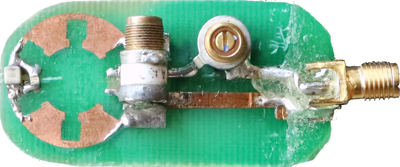
A prototype of the magnetron surface coil was built, including six vane-type slots and total coil radius of 20 mm. The prototype was constructed using copper sheets laminated onto a nonconductive board. Tuning and matching capacitors (0–15 pF: Voltronics Co. Salisbury, MD, USA) were soldered directly onto the surface: two parallel ceramic capacitors (American Technical Ceramics, Huntington Station, NY, USA) were placed as shown in Fig. 1. The coil prototype was then matched and tuned to 50 Ω and 500.32 MHz, respectively (proton frequency for 11.7 T). The signal received by the coil was conducted to an MR imager port via a 50-Ω-coaxial cable attached to the prototype coil. The quality factor (Q) of the coil was measured with a network analyzer (R&S-ZNB4, Rohde&Schwarz GmbH & Co., Munich, Germany) divided by 3-dB bandwidths, with a quarter-wavelength coaxial cable at the input of the coil. Coil performance was measured via the Q. Then, the loaded value was measured while the coil was placed on top of a saline solution-filled spherical phantom (20-mm radius). A commercial circular-shaped coil with a 20-mm diameter was also used for comparison reasons (Bruker Co, Ettlingen, Germany). The two coil designs were operated in transceiver mode. We performed phantom imaging experiments with a CuSO4 x 2H2O phantom on a 11.7T/16cm preclinical imager (BioSpec, Bruker Co, Ettlingen, Germany) using a standard gradient echo sequence (FLASH sequence). The following acquistion parameters were used: TE/TR=4/300ms, NEX=4, Flip Angle= 300, size=256x256, slice thickness = 1 mm, NEX = 4.Discussion
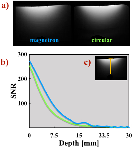
The quality factors of magnetron coil were approximately: Qu/Ql=50.76/7.83, giving Ql 6.5 = Qu. The noise figure (NF) was also computed for our coil using these Q values above giving 1.6. This bench test results and the NF show a good performance of the magnetron design. Phantom images were acquired with both coil designs and shown in Figure 2.a). The signal-to-noise ratios (SNR) were also calculated using the image data. The SNR values for the coils were; magnetron coil: 34.36 and circular coil: 26.82. The magnetron coil has a SNR improvement of 28.14 % over the popular circular coil. Fig. 2.b shows a SNR roll-off comparison of the magnetron (blue) and circular (green) coils acquired from the phantom images. The experimental data were indicated by the yellow line Fig. 2.c. The SNR versus depth profiles show that the magnetron coil design has an incremental increase on SNR values compared to the circular coil, for points for over 1 cm away from the coil plane. The results also confirm the findings previously reported [2-4]. This coil design is also able to outperformed the circular coil for preclinical studies at 11.7 T. These experimental results demonstrate the versatility and feasibility of the magnetron design to be used at UHF MRI.Acknowledgements
This works was supported by CONACYT Mexico (grant number 112092) and, (PAPIIT) UNAM (grant number IT 102116) & PAPIME UNAM (grant number PE104117). Also we thank Dr. D. Padro for his assistance to acquire the images.References
1. Budinger, T. F. Polenova, T. J Mag Reson (2016) 266: 81. https://doi.org/10.1016/j.jmr.2016.01.008
2. Rodriguez, A. O. Arch Med Res. (2006) 37: 804. http://dx.doi.org/10.1016/j.arcmed.2006.01.010
3. Solis, S. E. et al. Phys Med Biol (2011) 56: 3551. https://doi.org/10.1088/0031-9155/56/12/007
4. Solis-Najera, S. E. et al. Magn Reson Mater Phy (2015) 28: 599. https://doi.org/10.1007/s10334-015-0501-8
Figures