1744
3-Fold SNR Enhancement of Small Animal $$${^1}{^3}$$$C MRI using a Cryogenically Cooled (88 K) RF Coil1Department of Electrical Engineering, Technical University of Denmark, Kgs. Lyngby, Denmark, 2Institut für Luft- und Kältetechnik gemeinnützige GmbH, Dresden, Germany, 3Electrical and Computer Engineering Department, University of Houston, Houston, TX, United States
Synopsis
SNR in hyperpolarized 13C MRI is often limited by the low sensitivity of the receive RF chain at the low Larmor frequency of 13C. In this study we present an RF transparent (non-metallic) cryostat designed for small animal imaging, which allows a coil temperature of 88 K, with a coil-to-sample distance below 3 mm. Performance of the cryostat equipped with a 30 x 40 mm2 13C surface coil (3 T, 32 MHz) was tested and 3-fold SNR gain over room temperature coil was achieved.
Purpose
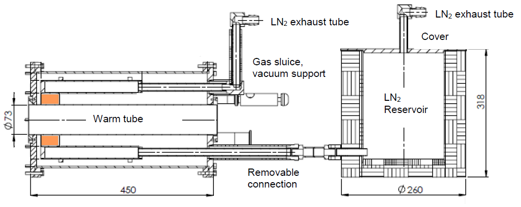
Cryogenically cooled coils have been a long-standing promise for SNR enhancement since the early days of MRI1. This is even more relevant nowadays, with the increased interest on imaging of low abundance nuclei with lower Larmor frequencies than protons2. However, the increased coil-to-sample distance needed in cryogenic coils can easily neutralize the SNR enhancement obtained by cooling. In this study we describe an MRI transparent cryostat for small animal imaging (Ø 73 mm) which allows a coil-to-sample distance below 3 mm, with the coil temperature reaching 88K while the outer surface being kept at room temperature.Methods
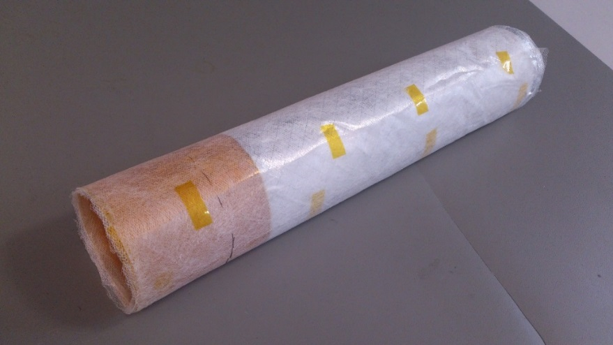
A schematic of the cryostat is shown in Fig. 1. A separate ceramic (Al2O3) cylinder (AdValue, AZ, USA) whose outer diameter matches the inner diameter of the vessel acts as a cold-finger for to-be-cooled RF coil(s). Besides the vacuum thermal insulation, additional Multi-Layer Insulation (MLI) was installed, to reduce radiation heat losses. A combination of traditional (aluminized Mylar) and non-metallic (Kapton) MLI was used, in order to avoid eddy currents close to the RF coil (Fig. 2). The cryostat (ILK, Dresden, Germany) is shown in Fig. 3a, while the cold-finger (with the RF coil attached) is shown in Fig. 3b. Temperature sensors were attached to the cold-finger, and to the outside the cryostat (at the animal position). The temperatures were monitored under two different situations: without heat externally applied to the inner bore, and with warm air (50 ℃) applied. The approximate amount of LN2 supplied during the experiment was 6 L. An octagonal 40x30 mm2 RF coil made of flat copper (thickness 1.2 mm) was glued to the cold finger using thermally conductive epoxy, and its Q-factor measured at room temperature and when cooled down inside the cryostat. A reference measurement with the coil immersed in LN2 was also performed. The coil includes tuning, matching and active decoupling as described in3. The SNR performance was measured with a combination of a spectrum analyzer (Keysight, CA, USA) and a signal generator (Rohde&Schwarz, Munich, Germany). A small pickup loop was placed inside the cryostat bore, at a distance of 38 mm to the coil, and excited with -100 dBm. The received signal was measured for two different cases: room temperature (290 K) and cooled (88K), and the SNR calculated.Results
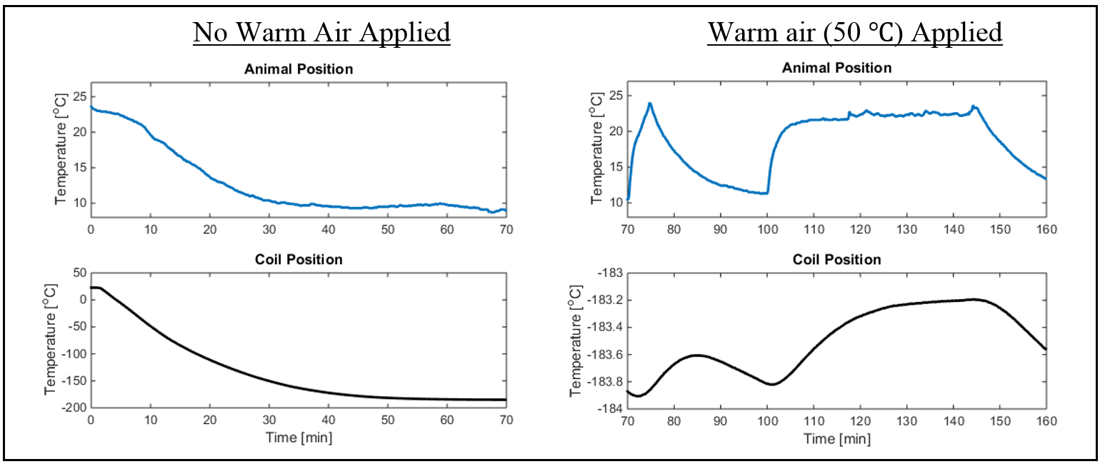
The measured temperature inside and outside the cryostat is shown in Fig. 4, where the warm air was applied for 5 min from minute 70 to 75, and later for a longer period of 50 min (from minute 100 to 150). It can be appreciated that the application of warm air, increases only minimally the temperature of the cold finger (0.6 K). The coil Q-factor is shown in Fig. 5.a). The Q-factor is increased from 325 to 599 when the coil is cooled, which agrees well with other results reported for coils of similar size4,5. The measured SNR is shown in Fig. 5.b.Discussion
The measured temperature at the coil position was 88 K (-184 °C), and this temperature could be kept stable for several hours (not shown in Figure 4). The temperature at the sample position was slightly decreased after some minutes to a stable value of about 10℃. This could be corrected by applying warm air at 50 ℃, with a minimal effect on the temperature of the cold-finger (and therefore on the coil). The relatively small difference between the measured Q-factor of the coil inside the cryostat, compared to the coil immersed in LN2 shows that the coil is indeed very close to the LN2 temperature (77 K). A 3-fold SNR enhancement was measured, which agrees well with the theoretically predicted value when sample losses are negligible $$$(ΔSNR = \frac{\sqrt{Q_{88K}·290}}{\sqrt{Q_{290K}·88}} = 2.6)$$$. The extra factor from 2.6 to 3 can be attributed to the noise reduction in the matching network, which was observed to effectively decrease the noise levels when cooled down.Conclusion
Cryogenically cooled RF receive coils can be the means to significantly improve SNR in 13C MRI, where sample noise is not very important. This is so, as long as the coil-to-sample distance is not increased excessively due to the thermal insulation needed to provide a warm environment at the sample position. In this study we describe a small animal cryogenic coil setup, where the coil can be kept at a distance below 3 mm from the sample, while keeping the sample position at room temperature. A 3-fold SNR enhancement is reported for a small 30x40 mm2 octagonal coil for 13C at 3T (32 MHz), which agrees well with the theoretically predicted value.Acknowledgements
No acknowledgement found.References
1. Black R, Early T, Roemer P, Mueller O, Mogro-Campero A, Turner L, et al. A high-temperature superconducting receiver for nuclear magnetic resonance microscopy. Science (80- ). 1993 Feb 5;259(5096):793–5.
2. Ardenkjær-Larsen JH. Increase in Signal-to-Noise Ratio of > 10,000 Times in Liquid-State NMR. Proc Natl Acad Sci U S A. 2003;100(18).
3. Sanchez-Heredia JD, Szocska Hansen ES, Laustsen C, Zhurbenko V, Ardenkjær-Larsen JH. Low-Noise Active Decoupling Circuit and its Application to 13C Cryogenic RF Coils at 3T. TOMOGRAPHY. 2017;3(1):60:66.
4. Wright AC, Song HK, Wehrli FW. In Vivo MR Micro Imaging With Conventional Radiofrequency Coils Cooled to 77°K. MRM. 2000;169:163–9.
5. Ratering D, Baltes C, Nordmeyer-massner J, Marek D, Rudin M. Performance of a 200-MHz Cryogenic RF Probe Designed for MRI and MRS of the Murine Brain. MRM. 2008;1447:1440–7.
Figures