1739
Design and evaluation of RF coils for hybrid MR-PET imaging of the prostate1Forschungszentrum Juelich, Juelich, Germany, 2Faculty of Medical Engineering and Technomathematics, FH Aachen University of Applied Sciences, Juelich, Germany, 3Faculty of Medicine, Department of Neurology, RWTH Aachen University, JARA, Aachen, Germany
Synopsis
Prostate cancer is one of the most common diseases in
Introduction
Simultaneously operating MR-PET hybrid clinical systems is gaining in interest since they provide valuable data with which, for example, to differentiate tumours from other lesions1. A human prostate is quite flexible and can move into different position under external conditions, such as patient position or insertion of an endorectal coil. Therefore, it is important to localise the critical region-of-interest using both MRI and PET under the same circumstances. An endorectal coil is commonly used to achieve a sufficient signal-to-noise ratio (SNR), since the prostate is positioned near the centre of the body2. Locating the PET detector close to the prostate also improves sensitivity and higher resolution3. This can be achieved by integrating the PET detector into the tube containing an RF coil. The tube can then be inserted into the patient in the same way as an endorectal coil. Another problem to be taken into account is bi-directional interference between PET to MR and MR to PET4. This requires complete shielding for the inserted PET system. Due to the space limitation, the shield is close to the RF coil, and consequently the efficiency of the RF coil can be significantly affected, leading to considerable SNR loss. In this work, we explore various coil designs suitable for use in MR-PET prostate imaging and investigate their performance by evaluating SNRs and penetration depths as a function of coil tilting angle against B0.Material and methods
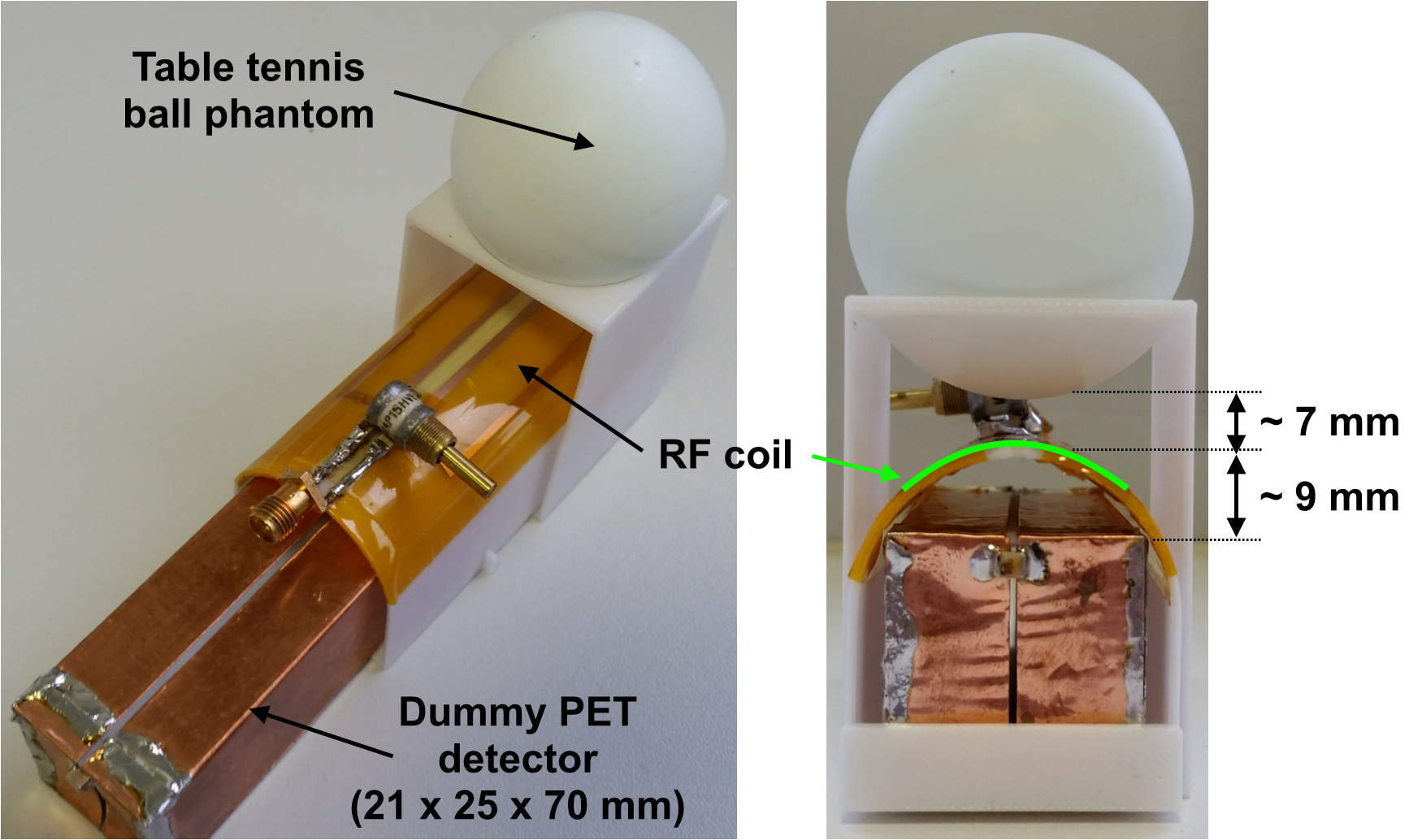
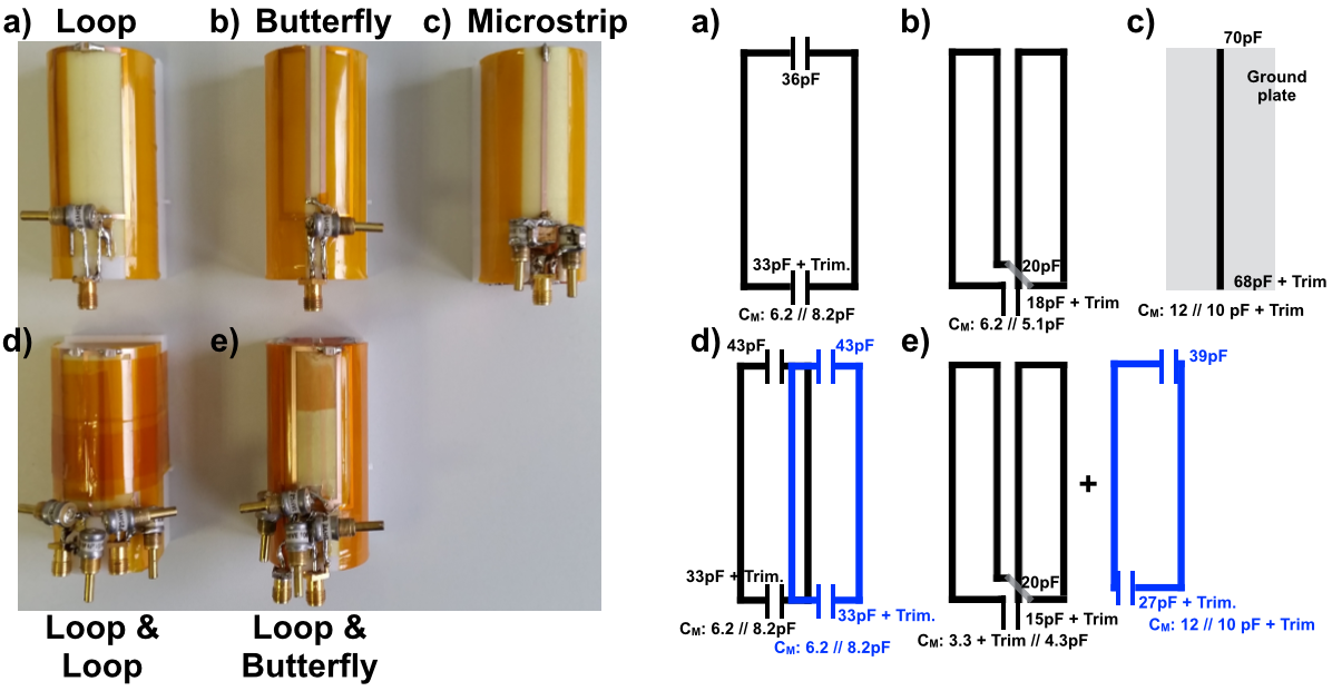
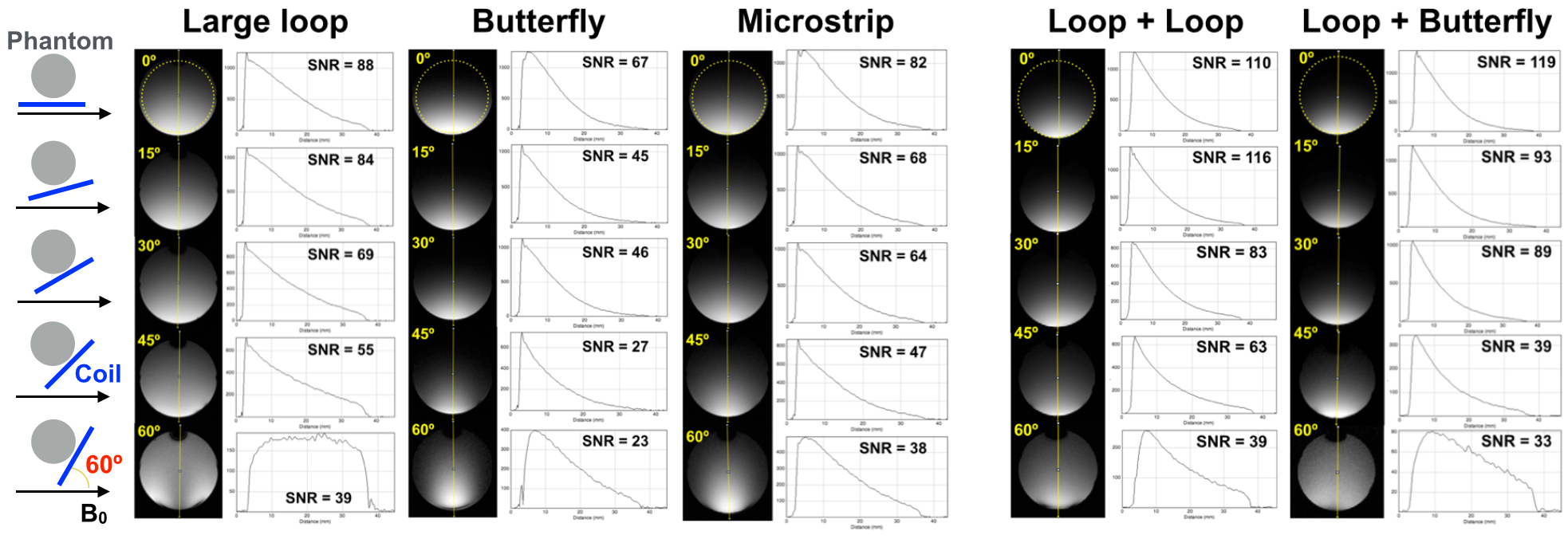
In order to characterise the performance of the coils independently, we built a shielded, dummy PET detector shown in Fig. 1 and used a table tennis ball phantom containing 3.75 g NiSO4 x 6H2O + 5 g NaCl per 1000 g H2O. The dummy PET detector was located under the coil former. Three commonly used coils were investigated: linear vertical (large loop), linear transverse (Butterfly and Microstrip) and quadrature coils constructed by combining the linear coils (overlapped loops and Loop+Butterfly). Due to the strong coupling, the Loop+Microstrip coil was excluded in this study. Fig. 2 shows photos of all coils and their equivalent circuits. The responses of these coils were measured on the bench using a network analyser. Two types T/R switches were used to drive the coil either in linear or in quadrature. All the capacitors were positioned outside the PET FOV to avoid any interruption in PET measurements and only thin and narrow coil patterns (copper) were within the FOV, which will not significantly degrade the PET performance5. All MR experiments were carried out on a 3T TRIO scanner using a 2D FLASH sequence (TR/TE = 12/4.19 ms, Averages = 8, 1:07 minutes scan time, slice thickness = 3 mm, matrix size = 256 x 256, FOV = 108 x 108 mm2). The coil and phantom were tilted by 0, 15, 30, 45 and 60º, and SNRs of all coils were measured and compared6. The acquired MR data were analysed using ImageJ and OsiriX software.Results
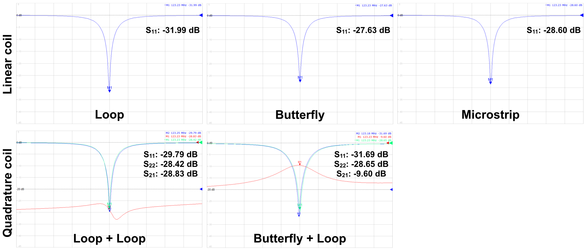
S-parameters of all coils were shown in Fig. 3 confirming that the coils were well tuned (< -25 dB). Figure 4 shows the results of SNRs and profiles acquired using the three linear and two quadrature coils with different tilting angles. On the left of Figure 4, the position of the phantom and coil itself, the tilting angles of the coil and B0 direction are indicated. It was found that SNRs of the large loop coil were higher than those obtained using the other linear coils, and as expected, SNRs of the quadrature coils were higher than those of the linear coils. SNRs of all coils were decreased with larger tilting angles.Discussion and conclusions
We have imaged and compared the outside region of the coils with different tilting angles to B0 in which the prostate may be located. It was found that the overlapped loops were, in general superior to the other coils, although in a certain angle, such as 30º, the Loop+Butterfly coil performed better in SNR. In this study, we focused only on comparison of the RF coil performance, so the set-up used here may not be the same as the final design. With this result, we therefore intend to exploit further studies with PET-MR hybrid systems in the future.Acknowledgements
No acknowledgement found.References
1. Neuner I, et al. Multimodal imaging utilising integrated MR-PET for human brain tumour assessment. Eur Radiol 2012;22:2568.
2. Pinkerton RG, et al. Transceive surface coil array for MRI of the human prostate at 4T. Magn Reson Med 2007;57:455.
3. Garibaldi F, et al. A novel TOF-PET MRI detector for diagnosis and follow up of the prostate cancer. Eur Phys J Plus 2017;132:396.
4. Akram MSH, et al. MRI compatibility study of an integrated PET/RF-coil prototype system at 3 T. J Magn Reson 2017;283:62.
5. Sander CY, et al. A 31-channel MR Brain array coil compatible with positron emission tomography Magn Reson Med 2015;73:2363.
6. Alfonsetti M, et al. Versatile coil design and positioning of transverse-field RF surface coils for clinical 1.5-T MRI applications MAGMA 2005;18:69.
Figures