1738
Concentric PET shields and wide-bore 1.5 T MR birdcage for optimal MR and PET signalDeb Rivera1,2, Erik R Huijing3, Cezar Alborahal2,4, Flavio Meliado3,5, Bart Steensma3, Thomas Dey6, Volkmar Schulz7, Björn Weißler7, E Versteeg3, Hugo de Jong3, Martino Borgo8, Michel Italiaander2, and Dennis Klomp2,3
1Academic Medical Center, Amsterdam (AMC), Amsterdam, Netherlands, 2MR Coils BV, Zaltbommel, Netherlands, 3University Medical Center Utrecht (UMCU), Utrecht, Netherlands, 4MR Focus BV, Zaltbommel, Netherlands, 5MR Code BV, Zaltbommel, Netherlands, 6Rheinisch-Westfaelische Technische Hochschule Aachen, Aachen, Netherlands, 7Rheinisch-Westfaelische Technische Hochschule Aachen, Aachen, Germany, 8Furtura, Heerhugowaard, Netherlands
Synopsis
Prioritizing signal fidelity for PET and MR, we simulated, built, and tested a wide-bore 1.5T body coil with a concentric ring of novel PET shields. With such an approach, the inherent reduced transmit efficiency can be compensated for by applying more power. Through B1+ measurements in phantoms and in the head, we validate that dual RF power amplifiers meet the power requirements.
Introduction
The goal of hybrid PET/MR is to co-register metabolic tags with MR images of high spatial resolution and inherent tissue-contrast, to pinpoint structure and function in disease. To date, hybrid PET/MR systems compromise either the signal of either the MR or the PET.1 For example, PET/MR with split-gradients2 prioritize PET signal over high-performance gradients critical for DWI and image acceleration. Other examples have reduced the bore size of the system to integrate the PET cameras (i.e. reducing the wide bore into a narrow bore MRI). We present an approach that does not degrade MR signal or PET signal, by incorporating the PET detectors in between the gradient RF shield and the RF transmit coil of the MR system, while maintaining a wide bore system. (Fig.1). The design in principle allows for the largest volume of PET detectors (and thus sensitivity) without comprising patient-bore/FOV. Building on our previous simulations of PET shield designs,3 we designed, simulated, implemented, and tested a 1.5 T wide-bore birdcage incorporating a full ring of PET shields (Ingenia, Philips Healthcare, Best), with the aim of creating a design capable of delivering similar B1+ as the conventional wide-bore birdcage within the power constraint of dual power-amplifiers.Methods
In order to accommodate the optimal number and size of PET detectors around a wide-bore birdcage former (703 mm diameter), a 42-rung high-pass quadrature birdcage (~64 MHz) was simulated and built. The PET shield units were designed to inhibit mirror currents and to fit within the confined space between the body coil and RF shield (743 mm diameter) (Fig.1). Simulations were done to evaluate performance with and without PET shields, modelling conductors (PET shielding, birdcage etc.) as perfectly electric conductors (PEC) with no additional resistive losses, and a 0.4 S/m body-mimicking cylinder (Sim4Life, Zürich Med Tech, Zürich). B1+ of the novel birdcage was performed by turning off power-optimization, and driving at a fixed maximum RF power of 18kW. The present study was approved by the internal review board and written informed consent was obtained from our volunteer.Results
Simulations indicate that the addition of PET shields gives an attenuation of <2 dB (B1+ of 80%) (Fig.2), as do B1+ measurements in a phantom and in the brain (Fig.3). Regions within the body remain predominantly above 70% (worst case 64%) of the B1+ attained by the clinically used wide-bore coil driven with 18 kW.Discussion and conclusions
A wide-bore 1.5 T MR birdcage with concentric PET shields was evaluated in simulations and experimentally. In order to achieve approximately the same B1+ as the clinical body birdcage coil with dual 36 kW power amplifiers, it is necessary that the hybrid coil provide at least 70% of the B1+ of the clinically used birdcage. Simulations and experimental results indicate that less than 2x power will be needed, as relative B1+ of 80% (attenuation <2 dB) requires 1.6x power as compared to the clinical coil. Combined PET/MR has been shown to outperform PET/CT for tumor metastases localization,4 allows differentiation of recurrent tumor and necrosis,5 and has the potential for parametric MR and PET as a method of virtual biopsy for treatment tracking in tumors.6 As compared to hybrid MR approaches with compromised or even split-gradient designs,2 the presented method lends toward gradient-intensive methods that unlock the benefits of PET/MR to improve tumor localization, attenuation correction, and biomarkers such as interleaved motion-tracking and parametric imaging such as DWI.5,6 Another group independently investigated PET detectors concentrically with the rungs of an unshielded (no local) birdcage head coil for 3T,8 as a hybrid head-insert PET detector and RF coil. However, the design of Akram et al required more than a four-fold increase in power (2x increase in SAR) to achieve the same B1+ as the coil without the integrated PET detectors. As indicated by preliminary simulations the extra deposited power, and corresponding voltages, are contained between the RF coil and RF shield, thus SAR is not expected to be a limiting factor. Based on the present study, placing PET detectors between the birdcage and RF shield seems a feasible approach to PET-MRI integration (Fig.4) and our results predict that the power needed to achieve the same B1+ as the conventional clinical coil can be met by the addition of a second and equal power amplifier.Acknowledgements
No acknowledgement found.References
- Vandenberghe, S., and Marsden, P.K. PET-MRI: a review of challenges and solutions in the development of integrated multimodality imaging. Physics in medicine and biology 60.4 (2015): R115.
- Poole, M., Bowtell, R., Green, D., Pittard, S., Lucas, A., Hawkes, R., and Carpenter, A. Split gradient coils for simultaneous PET-MRI. Magn Reson Med. 2009 Nov; 62(5): 1106–1111.
- Versteeg, E., Steensma, B.R., Raaijmakers, A.J.E., Luijten, P.R., van den Berg, C.A.T., Klomp, D.W.J. Integrating PET detectors in a wide bore 1.5 T MR system: a simulation study. ISMRM Benelux Chapter 2017.
- Melsaether, A., Pujara, A.C., Pysarenko, K., Raad, R.A., Ponzo, F., Friedman, K., Chandarana, H., Jhaveri, K., Sigmund, E., Kim, S., and Moy, L. Whole body 18FDG-PET/MRI as compared with 18FDG-PET/CT in metastatic breast cancer, ISMRM 2014.
- Huo, E., Wilson, D.M., Eisenmenger, L., Hope, T.A. The Role of PET/MR Imaging in Precision Medicine. PET Clin. 2017 Oct;12(4):489-501. Rosenkrantz, A.B., Friedman, K., Chandarana, H.,
- Melsaether, A., Moy, L., Ding, Y., Jhaveri, K., Beltran, L., and Jain, R. Current Status of Hybrid PET/MRI in Oncologic Imaging. Am J Roentgenol . 2016 January ; 206(1): 162–172.
- Iida, H., Kanno, I., Miura, S., Murakami, M., Takahashi, K., Uemura, K., A Simulation Study of a Method to Reduce Positron Annihilation Spread Distributions Using a Strong Magnetic Field in Positron Emission Tomography, IEEE Transactions on Nuclear Science 33(1):597 - 600 · March 1986.
- Akram, M.S.H., Obata, T., Suga, M., Nishikido, F., Yoshida, E., Saito, K., Yamaya, T. MRI compatibility study of an integrated PET/RF-coil prototype system at 3T. J Magn Reson. 2017 Oct;283:62-70.
Figures

Fig.1 PET shield design (a) and implementation (b).
(c) Full ring of PET detector shields fit between the fiberglass former of the
body birdcage and the RF gradient shield, a gap of 2 cm. (d) Birdcage with
integrated PET shields installed in scanner bore.
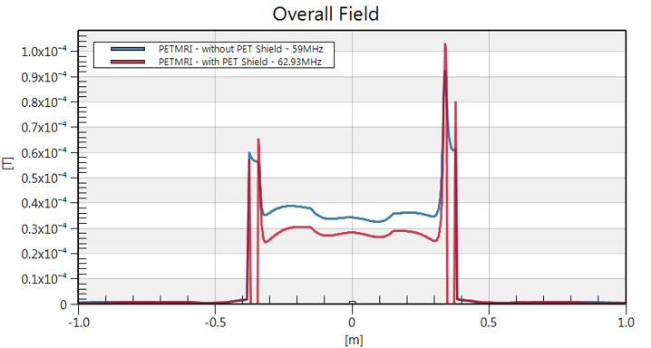
Fig.2 B1+ vs. position along the center of the
42-rung bird with and without shield. The resonance
frequency of the homogeneous mode and the
field were extracted from each of the
simulations for an input power of 18 kW, loaded with a body-mimicking cylinder
with 0.4 S/m. PET shields cause less than 2 dB attenuation.

Fig.3 B1+ maps for 20-cm sphere phantom (water
with ~0.3% H2SO4 and ~0.05% CuSO4) (left) and head (right), with 80% B1+ as
compared to commercial birdcage bore coil indicated as a white horizontal line
in both.
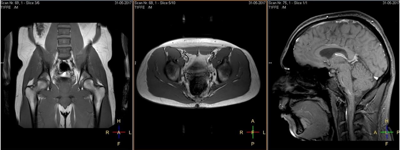
Fig.4 Scout images of body and head acquired with
the wide-bore PETMR body coil. Images acquired of a volunteer: 2-mm isotropic
in-plane resolution, 10-mm slice thickness, TR/TE of 113/5.7 ms, flip angle
circa 10-degrees, total acquisition 23 s.