1737
Development of a radiolucent 64-channel on-body receive array to enhance image quality of the MR-linac1Radiotherapy, UMC Utrecht, Utrecht, Netherlands
Synopsis
To improve the spatiotemporal resolution of 3D imaging on the MR-linac, we are developing a new radiolucent 64-channel receive array, which can be placed directly onto the patient during treatments. Coil prototypes caused no significant dosimetric changes. Measurements with 4-channel prototypes showed that overlapping coil loops lead to the highest potential imaging performance. Imaging comparisons with the current MR-linac array showed that the signal-to-noise ratio is improved.
Introduction
The current receive arrays of the 1.5T MR-linac contain only four channels each. Additionally, the anterior array is elevated several centimeters above the patient to avoid anatomy deformations and minimize the skin dose.1 To increase the image quality and acquisition speed that are required for 3D monitoring of the anatomy and subsequent adaptive dose delivery, we are developing two radiolucent 32-channel receive arrays for placement directly onto the patient. However, coils in the MR-linac are irradiated through and consequently no electric components are allowed in the irradiation window, as they distort the photon beam. This complicates the coil design, e.g. no segmented placement of tuning capacitors is possible.
In this work we assess the dosimetric impact of various coil materials and optimize the radiolucent design of the receive array. Furthermore, we compare the imaging performance of arrays with overlapping loops and adjacent loops with the current anterior MR-linac coil.
Methods
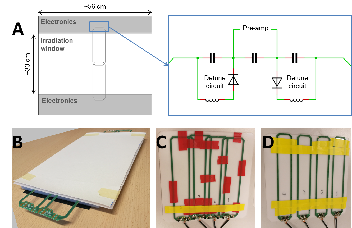
The 64-channel receive array will comprise of two 32-channel arrays. Two rows of 16 elements each should result in an electric-component-free area of approximately 30×56 cm2 (Figure 1a), enabling usage of parallel imaging in feet-head direction.
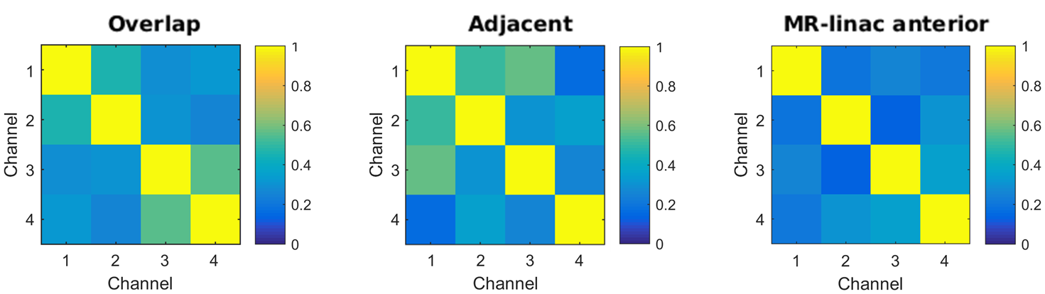
Prototypes: a 2×2 element prototype for dosimetry was created with five layers: leather, plastic support, copper loops, foam, and leather again (Figure 1b). The low (electron) density foam serves as a spacer between the material with high electron density (i.e., copper and plastic) and the patient’s skin to minimize skin dose. A 15 mm foam layer was found to optimally decrease the surface dose (results not shown). Consequently, two 1×4 element prototypes with 15 mm foam were created for imaging purposes. In one prototype 5 cm wide loops were overlapped (Figure 1c) to minimize inductive channel coupling. The other prototype consisted of four non-overlapped (adjacent) loops (Figure 1d). Cable lengths were adjusted to add preamp decoupling. Coil coupling was quantified from the noise-only pre-scan by calculating the Pearson correlation coefficients of the array.
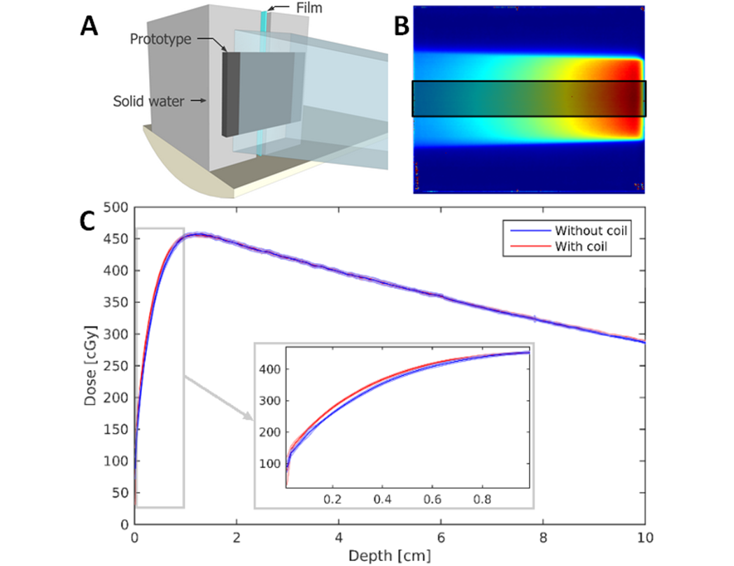
Dosimetry: all dosimetry and imaging experiments are performed on a 7 MV MR-linac system (Unity, Elekta, Crawley, UK) with the 1.5T magnetic field present. A vertically positioned GAFCHROMIC (Ashland, Bridgewater, NJ) EBT3 film between blocks of solid water was irradiated with a 500 MU, 10×10 cm2 field with and without the 2×2 element prototype present (Figure 2a). Depth-dose curves were generated by averaging 200 lines in the center of the beam profile (Figure 2b).
Imaging: all imaging data is acquired using a Philips (Best, NL) geometry phantom (⌀ = 400 mm, h = 125 mm). The raw k-space data is reconstructed using ReconFrame (Gyrotools, Zurich, CH) to omit all unnecessary processing steps. Sum-of-squares coil combination was used. The signal-to-noise ratio (SNR) was calculated from a 50-dynamic gradient echo acquisition (TE/TR = 4.0/30 ms, FOV = 420×240 mm2, voxel size = 3×3×10 mm3):$$SNR(x,y)=\frac{p_{mean}(x,y)}{p_{SD}(x,y)},$$where pmean(x,y) and pSD(x,y) are, the mean and standard deviation of the pixel intensity over time at location (x,y), respectively.
Results
Dosimetry: the depth-dose curves with and without the coil (Figure 2c) show maximal dose differences of 17.9 cGy (<4% of the maximal dose) in the build-up region. From a depth of 1 cm the curves overlap. Furthermore, direct surface dose increases due to the coil prototype (results not shown) were found to be much smaller than those caused by the treatment table.
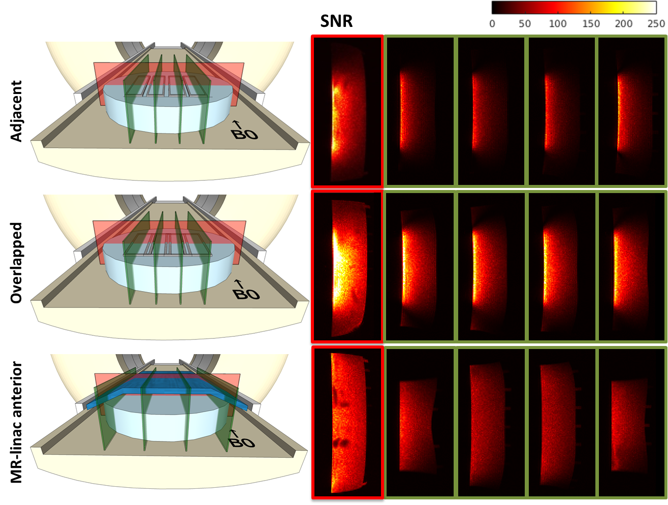
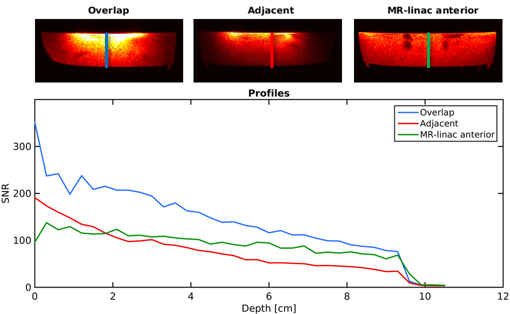
Imaging: SNR maps are shown in Figure 3. The overlapped prototype shows the highest SNR increase compared to the current MR-linac coil: from >200% at the surface to 44% at a depth of 7 cm. Profiles of the SNR over the depth of the prototype are shown in Figure 4. Coil coupling is visualized in the noise correlation maps (Figure 5).
Discussion
Dose increases in the depth-dose curves of <5% before the dose maximum and the lack of dose difference deeper than 1 cm suggest that on-body placement of a receive array during a treatment in the MR-linac is feasible. Furthermore, coil-induced body deformations can be compensated for with online replanning.2
The overlapped prototype shows the highest SNR profile. A 64-channel array with overlapping loops should therefore lead to the the largest SNR improvement compared to the current array. Coil decoupling is most optimal in the MR-linac’s anterior array, as the smaller loops of our prototypes are in closer proximity.
Currently, we are expanding the array and work towards two arrays with 32 channels each. This should enable usage of higher acceleration factors, which will result in faster imaging during treatments.
Conclusion
A 64-channel array that is placed on the patient can strongly improve the imaging performance of the MR-linac for high spatiotemporal monitoring of the 3D anatomy during treatments, while the array does not interfere with the dose delivery.Acknowledgements
This work is part of the research program HTSM with project number 15354, which is (partly) financed by the Netherlands Organization for Scientific Research (NWO).References
1. Raaijmakers, A. J. E., Raaymakers, B. W. & Lagendijk, J. J. W. Integrating a MRI scanner with a 6 MV radiotherapy accelerator: dose increase at tissue-air interfaces in a lateral magnetic field due to returning electrons. Phys. Med. Biol. 50, 1363–1376 (2005).
2. Kontaxis, C., Bol, G. H., Kerkmeijer, L. G. W., Lagendijk, J. J. W. & Raaymakers, B. W. Fast online replanning for interfraction rotation correction in prostate radiotherapy. Med. Phys. 44, 5034–5042 (2017).
Figures