1736
Ultra-low power transmitter for encoding non-MR signals in Magnetic Resonance (MR) recordings1Department of Electrical Engineering, Technical University of Denmark, Kgs. Lyngby, Denmark, 2Research Centre for Magnetic Resonance, Dept 714 Centre for Functional and Diagnostic Imaging and Research, Copenhagen University Hospital Hvidovre, Hvidovre, Denmark
Synopsis
Advancing Magnetic Resonance Imaging (MRI) technology requires integration of the MRI scanners with sensors and systems for monitoring various non-MRI signals. In this paper, we present design and integration of a low power AM radio transmitter into a 3T MRI scanner, which can be used for efficient collection of data from non-MRI sensors. The transmitter consumes only 1.3mW while transmitting 2.7µW at 120MHz with high frequency stability. The presented design is useful in low power applications requiring high frequency stability and is intended for wireless transmission of non-MR signal recordings during MRI scanning.
INTRODUCTION
Nuclear magnetic resonance (NMR) is extensively used for chemical analysis and magnetic resonance imaging (MRI). A wide range of MRI methods are used for medical diagnosis. Image quality varies with the patient’s ability not to move while recording data. Respiration and other motion can significantly degrade image quality. That can be improved by independently measuring motion of the patient and using these recordings for correcting the images [1]. Other non-MR recordings are also of interest during scanning, e.g., references for calibration of MR signal strength (ERETIC, [2]), electrophysiological recordings or temperature measurement [4]. Combining imaging data and independently measured non-MR data is challenging, because it has to be done with a high temporal precision, e.g. for motion and electrophysiology. By encoding non-MR recordings directly into imaging data, the synchronization can be ensured and correlation facilitated [3].
To make the non-MR signal source wireless and easy to operate, it is advantageous to have a low power transmitter running in the low mW range at a frequency slightly outside the MR signal range, but within the detection range of the scanner. This approach requires precise placement of the non-MRI signal in the recorded spectrum of the scanner. Therefore, one of the key requirements to the transmitter is high frequency stability. The transmitted RF power needed is in the µW range, because the MRI scanner is an extremely sensitive radio receiver. For the same reason, the transmitter antenna can be small with a poor gain. This paper describes the design and implementation of such a low power frequency stable transmitter for non-MR measurements with the specification summarized below.
Carrier frequency 120.0MHz
Frequency stability better than ±40ppm
Output power 3µWPower consumption 6.5V / 200µA
CIRCUIT DESIGN
The requirement for low power consumption prevents using off-the-shelf integrated transmitters and limits the number of active components used in the circuit. For that reason, a single transistor topology has been chosen. The heart of the transmitter is a Colpitt oscillator with modifications allowing amplitude modulation, see Fig. 1.
One of the design challenges is to provide frequency stability of the oscillator. It was found that a conventional LC resonator cannot provide the required frequency stability, a crystal must be used. The crystal QCL24.0000F18B23B made by QANTEK Technology Corporation is made for 24MHz fundamental frequency mode operation, but is used at the 5th overtone in this design.
TEST IN A 3T MRI SCANNER
The transmitter was tested in a Philips Achieva 3T MRI scanner using echo planar imaging (EPI) with 233kHz/1.6kHz total readout and phase encoding bandwidths, respectively (horizontal and vertical directions in the figures). A 0.26m dipole antenna was used to transmit into the MRI scanner, not tuned for 120MHz. A non-tuned antenna was chosen to partly reject the very powerful RF impulses made by the MRI scanner. These can damage the transmitter and were partly turned off during the measurements. The non-tuned antenna decreased the power transmitted to the MRI scanner, but with its high sensitivity, this is not an issue.
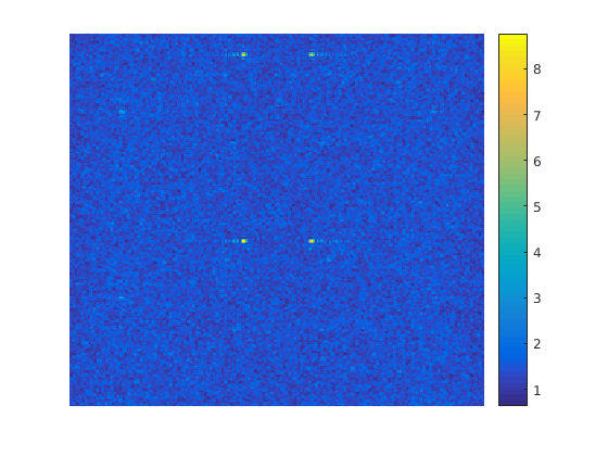
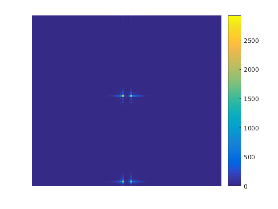
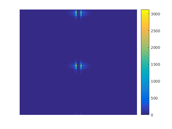
Three recorded images are shown for demonstration: One with the transmitter turned off (Fig. 3), one with no AM modulation (Fig. 4) and one with a 3.0V amplitude, 10Hz sine wave AM signal (Fig. 5). Image recording time is 79ms and the color bars indicate signal strength in arbitrary units, consistent between images.
The first image, Fig. 3, shows background thermal noise and weak irrelevant noise sources near the recording frequency that is outside the MR signal bandwidth. The thermal noise is clearly visible in the image, which is an indication of the low signal. The second image, Fig. 4, shows the transmitter’s single-frequency signal , appearing as four dots with asymmetric ringing. This is expected when considering the EPI image calculation algorithm [3]. The thermal noise is not visible, showing that the transmitter signal is much more powerful than the background noise, i.e. the signal to noise ratio is high. The last image, Fig. 5, shows the transmitter signal with 10Hz AM, where the four dots are broadened, reflecting broadening of the frequency spectrum. Encoded signals can be extracted by analysis of the scanner’s raw data [3].
CONCLUSIONS
A low-power crystal-controlled oscillator for encoding of non-MR signals in MR-recordings was built and tested. Power consumption and RF output power in the mW and µW ranges, respectively, were demonstrated. The weak transmitted signal was received by an MRI scanner with a high signal-to-noise ratio. The amplitude modulation was clearly visible in the MRI image.Acknowledgements
Jan Raagaard Petersen is funded by Danish National Research Foundation (DNRF124). Jan Ole Pedersen receives funding from the Sino-Danish Center for Education and Research.References
[1] Thomas Koesters, Ryan Brown, Tiejun Zhao, Mattias Fenchel, Peter Speier, Li Feng, Yongxian Qian, and Fernando Emilio Boada, Motion Correcting Complete MR-PET Exams Via Plot Tone Navigators, Proc. Intl. Soc. Magn. Reson. Med. 24:4250 (2016).
[2] Laurent Barantin, Alain Le Pape, Serge Akoka, A New Method Metabolites for Absolute Quantitation of MRS, Magnetic Resonance in Medicine 38:179-182 (1997).
[3] Lars G. Hanson, Torben E. Lund, Christian G. Hanson, Encoding of Electrophysiology and Other Signals in MR Images, Journal of Magnetic Resonance Imaging 25:1059–1066 (2007).
[4] Dah-Juyy Wang, John S. Leigh, Wireless Precision Piezoelectric Thermometer Using an RF Excitation-Detection Technique with an NMR Probe, Journal of Magnetic Resonance Imaging. Series B 105, 25-30 (1994).
Figures