1735
MR-Compatible, Organic Light-Emitting Diode (OLED) display for functional MRIYunKyoung Ko1, Seond Dae Yun1, Jörg Felder1, Chang-Hoon Choi1, and N.Jon Shah1
1Institute of Neuroscience and Medicine - 4, Juelich, Germany
Synopsis
Functional MRI (fMRI) frequently relies on visual stimulation. In this study, we designed and implemented a MR compatible display unit based on organic light-emitting diodes (OLED) and evaluated its performance on a 3T clinical MRI scanner by carrying out a visual block-paradigm fMRI experiment using the OLED display. The OLED display was successfully operated during the MR measurements. And an fMRI examination was successfully demonstrated with a visual functional study using the OLED display.
Purpose
Functional MRI (fMRI) is widely applied for brain activity research. It frequently relies on visual stimulation, such as projectors, LCD screens, and goggle systems. These display devices have some limitations relating to non-constant colour temperature, high power consumption, and narrow viewing angle.1 In this study, we designed and implemented a MR compatible display unit based on organic light-emitting diodes (OLED) and evaluated its performance on a 3T clinical MRI scanner by carrying out a visual block-paradigm fMRI experiment using the OLED display.Methods
The setup used a commercially available 5.5” full high definition active matrix OLED module (YANIN ELECTRONICS, China) with a resolution of 1920 x 1080, as shown in Fig. 1(a), and was connected to a computer via an MIPI-to-HDMI converter board. A USB power cable was used to supply power to the converter board and the OLED module, as shown in Fig. 1(a). The OLED module and the converter board were shielded to prevent RF interference (Fig. 1(b)). As shown in Fig. 1(c), the shield box was constructed using a transparent acrylic panel and a transparent conductive mesh (8900 Conductive Mesh, Hollandshielding, Netherlands). The selected mesh structure achieves a broadband shielding effectiveness of 60 dB (or better), while maintaining good visual transparency. The plastic housing used to cover the shield box was constructed using a 3D printer and copper tapes. The display module was connected via an optical HDMI cable. The OLED display, enclosed by the shield box, was installed at the edge of the MRI bore. A magnifying glass was used to overcome the small size of the display (Fig. 2), and viewing was made possible through a mirror placed on the head coil. To measure the noise generated by the OLED module, converter board, and cables, SNR was measured with and without operation of the OLED module. All scans were performed on a Trio 3T MRI (Siemens Healthineers, Erlangen, Germany) with a 32-channel head coil. A 170 mm spherical water phantom was used, and data acquisition employed a GRE sequence. The sequence parameters were: TR = 40 ms, TE = 3.84 ms, matrix size = 128 × 128, BW = 260 Hz/Px and FA = 25 deg. To evaluate the performance of the OLED display for fMRI, a visual functional study was carried out. A visual checkerboard paradigm was shown to activate the visual cortex. A healthy volunteer (age: 40 years) participated in the study and written, informed consent was obtained. For the subject, 75 volumes of fMRI data were acquired using an EPI sequence (TR = 2000 ms, TE = 30 ms, matrix size = 64 × 64, number of slices = 33, slice thickness = 3 mm, BW = 2260 Hz/Px).Results
The OLED display was successfully operated during the MR measurements. Fig. 3 shows GRE images acquired with and without the OLED display (a: turned off, b: turned on and unshielded HDMI cable, c: turned on and shielded HDMI, d: turned on and optical cable). When the OLED and HDMI cable were used, 90% SNR degradation was observed, as shown in Fig. 3(b). The SNR was improved by using the shielded HDMI cable (Fig. 3(c)). However by using an optical HDMI cable, the SNR was only degraded about 3% compared to the reference. As shown in Fig. 4, visually induced brain activations were successfully observed around the visual cortex, confirming the visual stimuli were successfully carried to the subject.Discussion
We have constructed and evaluated an MR compatible 5.5” OLED display for fMRI studies using the commercially available OLED module and the HDMI to MIPI converter board. A shield box was designed and implemented to prevent interference from the display and module, and to avoid any potential damage from RF transmission of MRI. An fMRI examination was successfully demonstrated with a visual functional study using the OLED display. The OLED supplied stable colour-temperature, high- resolution, and high contrast video images during the fMRI examination. Furthermore, this unit can include a curved feature and has the potential for use with virtual reality capable goggle systems inside the MRI bore.Acknowledgements
No acknowledgement found.References
1. Ced Yuen, OLED vs LED LCD: Which is the best disply technology? Trusted Reviews September 12, 2017. http://www.trustedreviews.com/opinion/oled-vs-led-lcd-2924602Figures
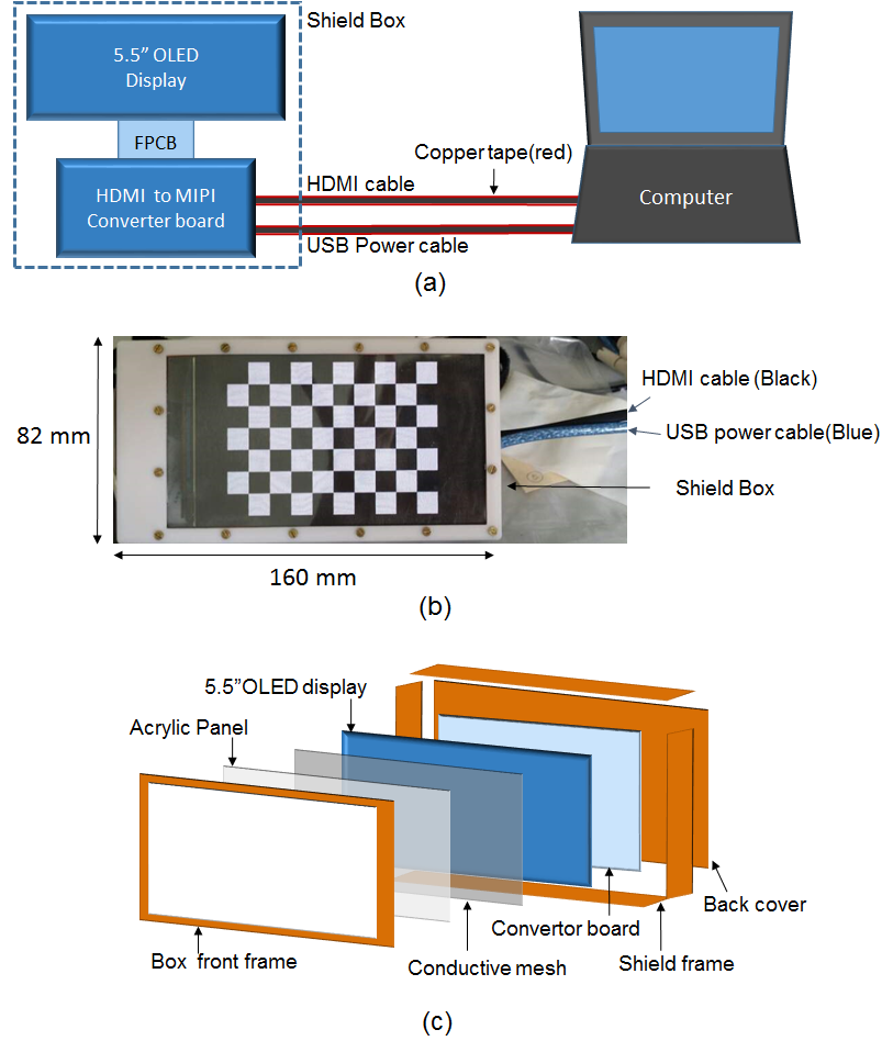
Figure 1:
(a) Connection between OLED display and PC, (b) OLED display, (c) Structure of
shield box
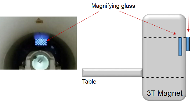
Figure 2:
OLED display and magnifying glass integrated in the 3T scanner
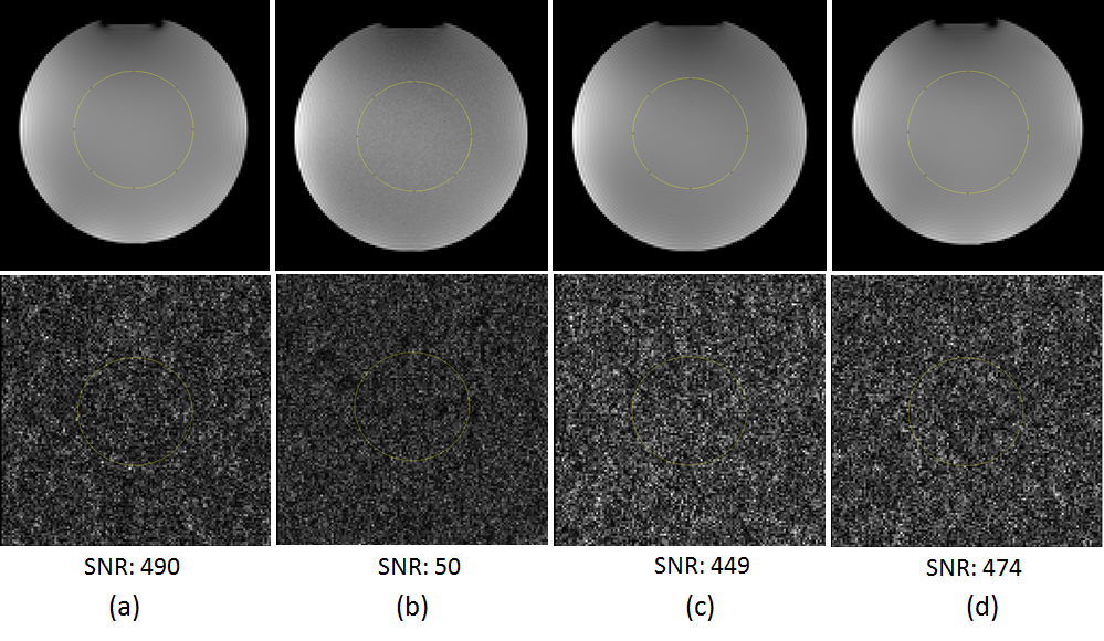
Figure 3:
GRE images and SNR evaluation: (a) reference, (b) with OLED ON and HDMI cable,
(c) with OLED ON and HDMI cable shielded with copper tape, (d) with OLED ON and
optical HDMI signal transmission
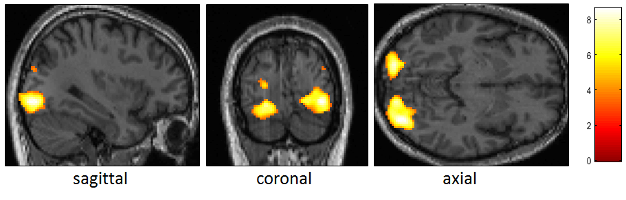
Figure 4:
BOLD activation when stimulating the visual cortex using the display presented
here and a checker board block paradigm.